Simulation
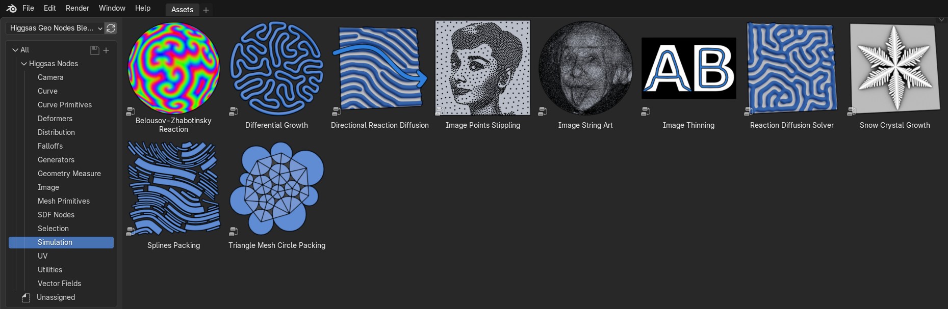
Belousov–Zhabotinsky reaction
Simulates oscillating reaction between 3 virtual chemicals

Belousov–Zhabotinsky reaction #geometrynodes #b3d pic.twitter.com/cFvZV4IFPJ
— higgsas (@higgsasxyz) October 23, 2024

- Color
Input color that reaction will happen
- Alpha
Scale of color R value
- Beta
Scale of color G value
- Gamma
Scale of color B value

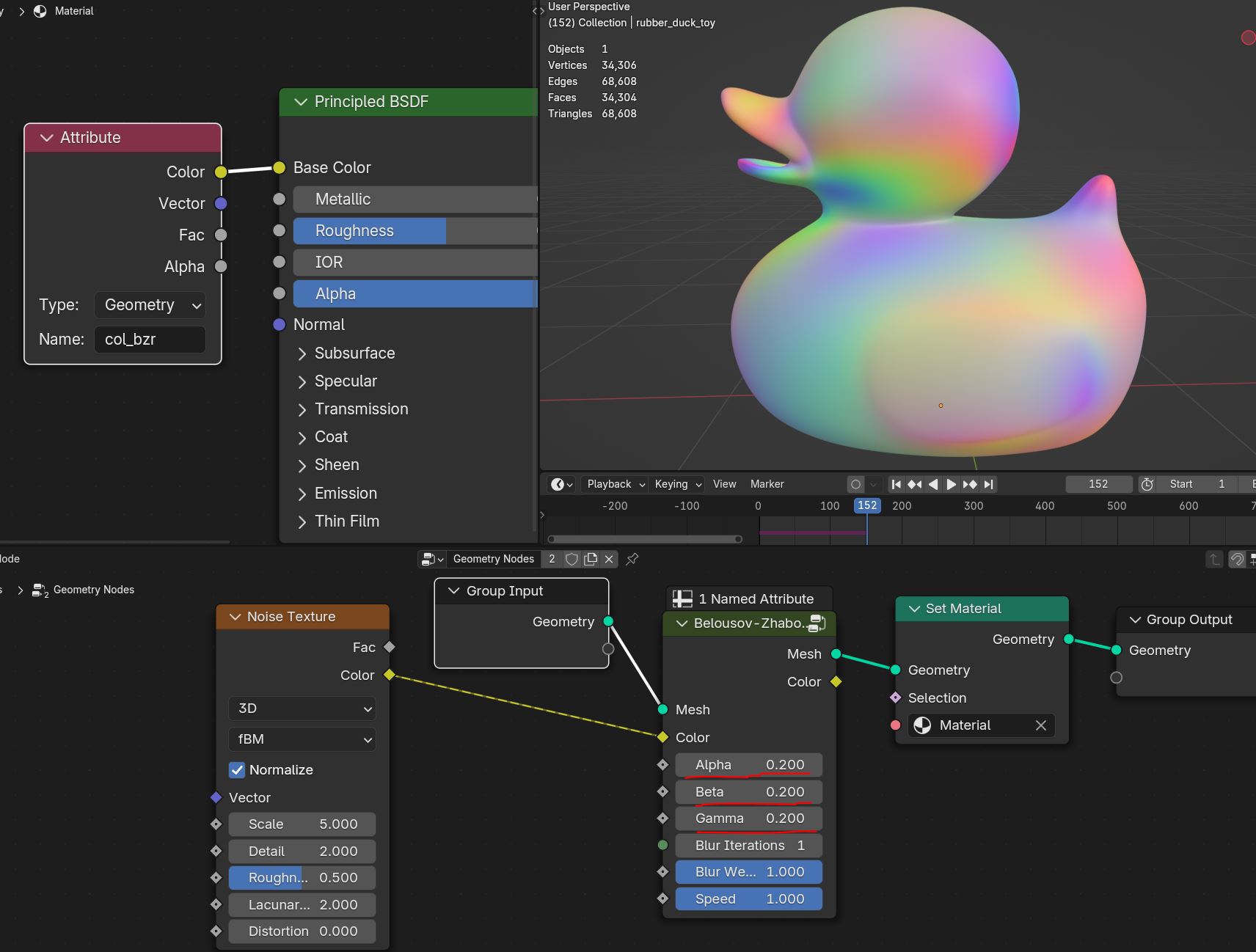
- Blur Iterations
How much chemicals will be averaged
- Blur Weight
Weight of the blur
- Speed
Speed of the simulation
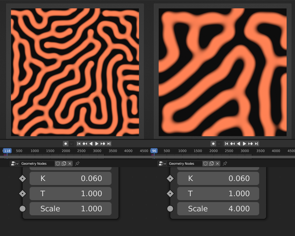
Directional Reaction Diffusion
Creates growing/mixing effect between two virtual chemicals with guide vector (Slower then regular Reaction Diffusion Solver)
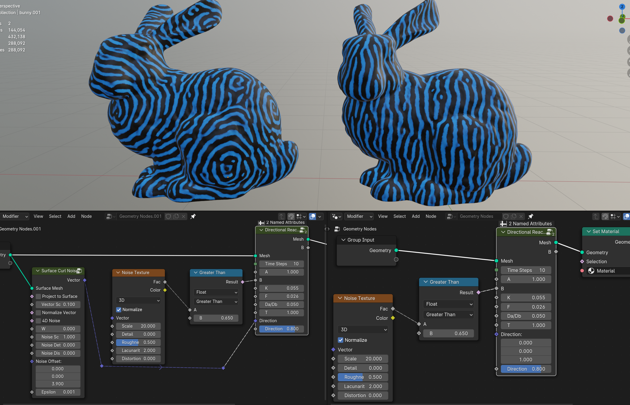
- A
Chemical A value stored on the mesh (set to 1)
- B
Chemical B value stored on the mesh (set it to some random texture/noise that effect will growth from)
- F
Chemicals feed rate
- K
Chemicals kill rate
- T
Time scale of the simulation (going above 1.5 simulation will become unstable)
Warning
For the effect in all directions mesh needs to be triangulated. Quad mesh direction can only go to the vertex neighbor
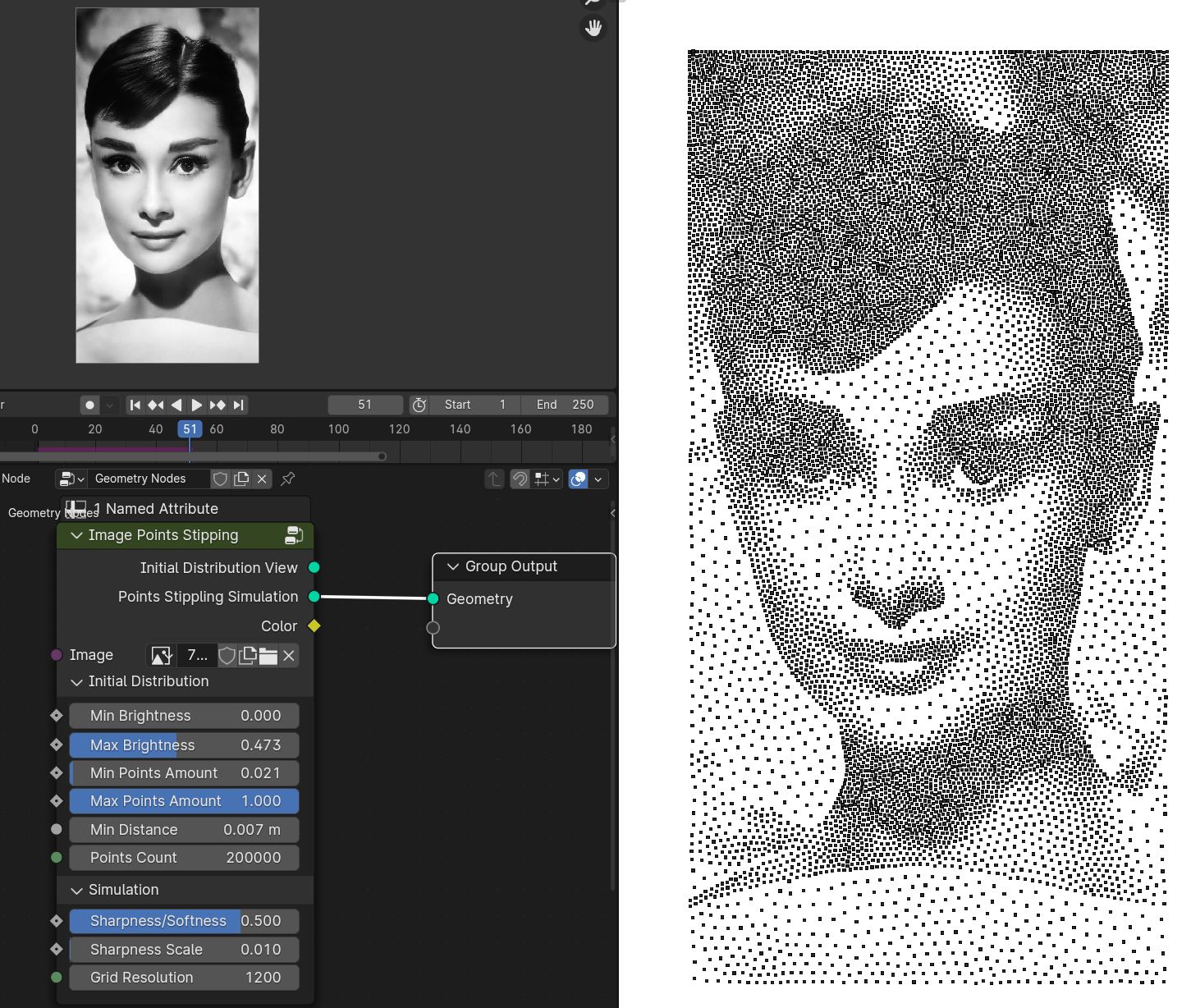
Image Points Stippling
Recreates image using point/dots for the gradiant shading using weighted voronoi technique
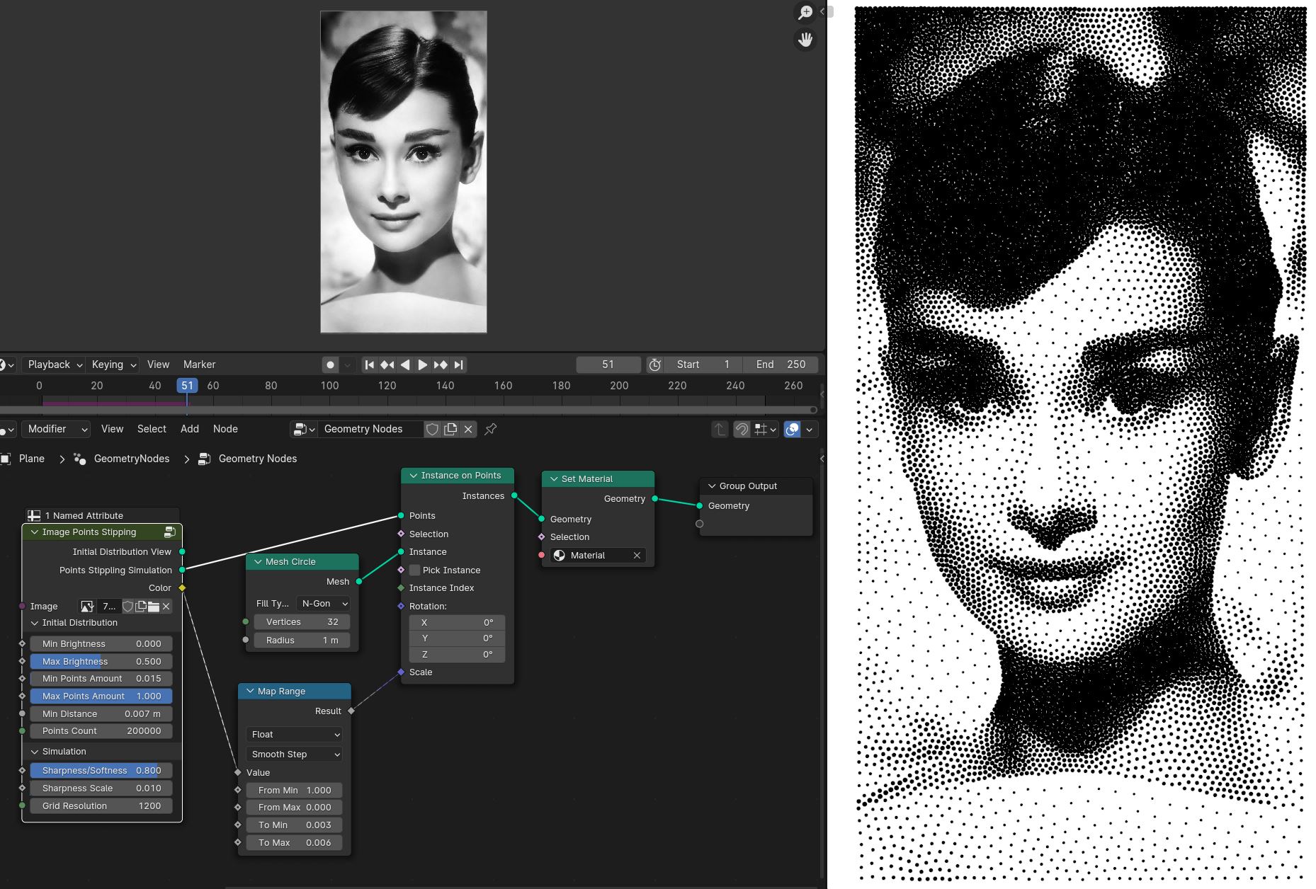
Setting up the solver
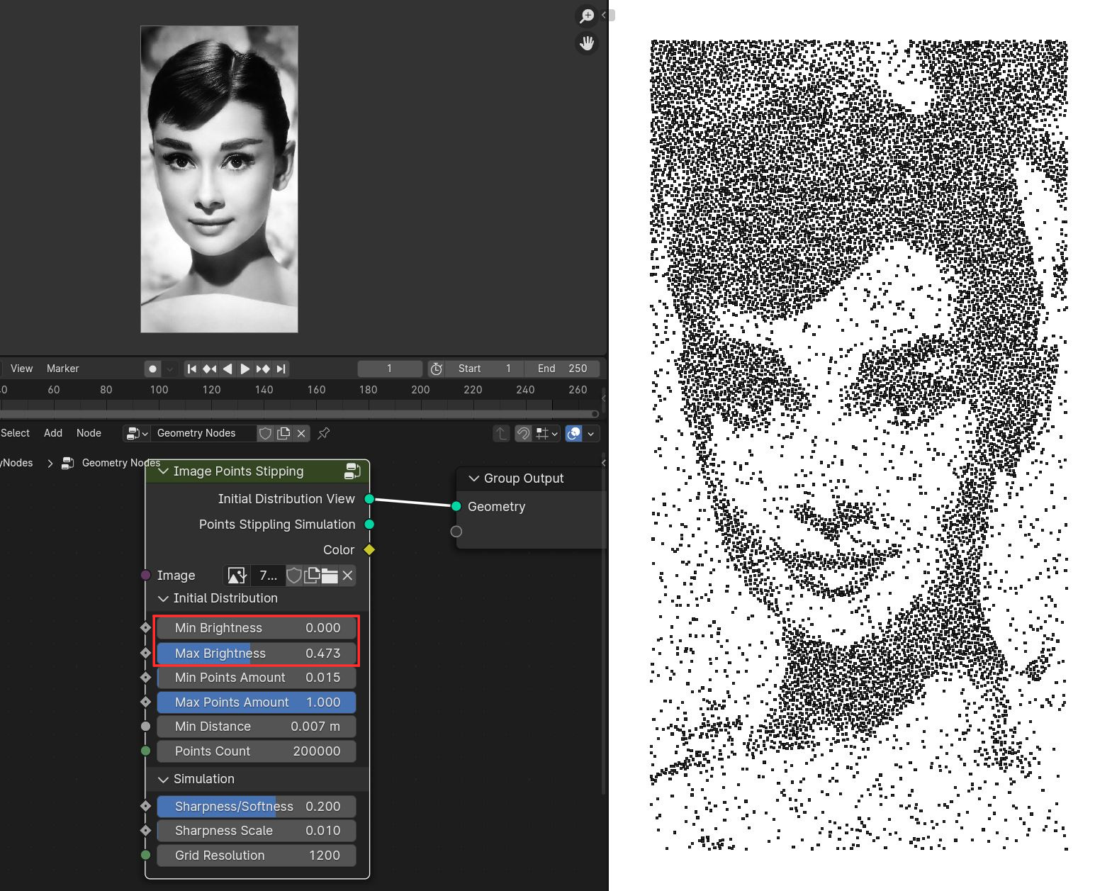
First open image of your choice
Connect Initial Distribution View to the Group Output or a viewer node
Adjust Min Brightness and Max Brightness to best match gradient of the image
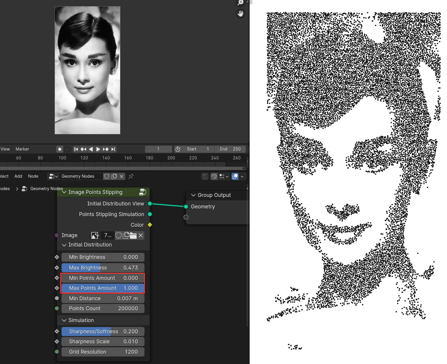
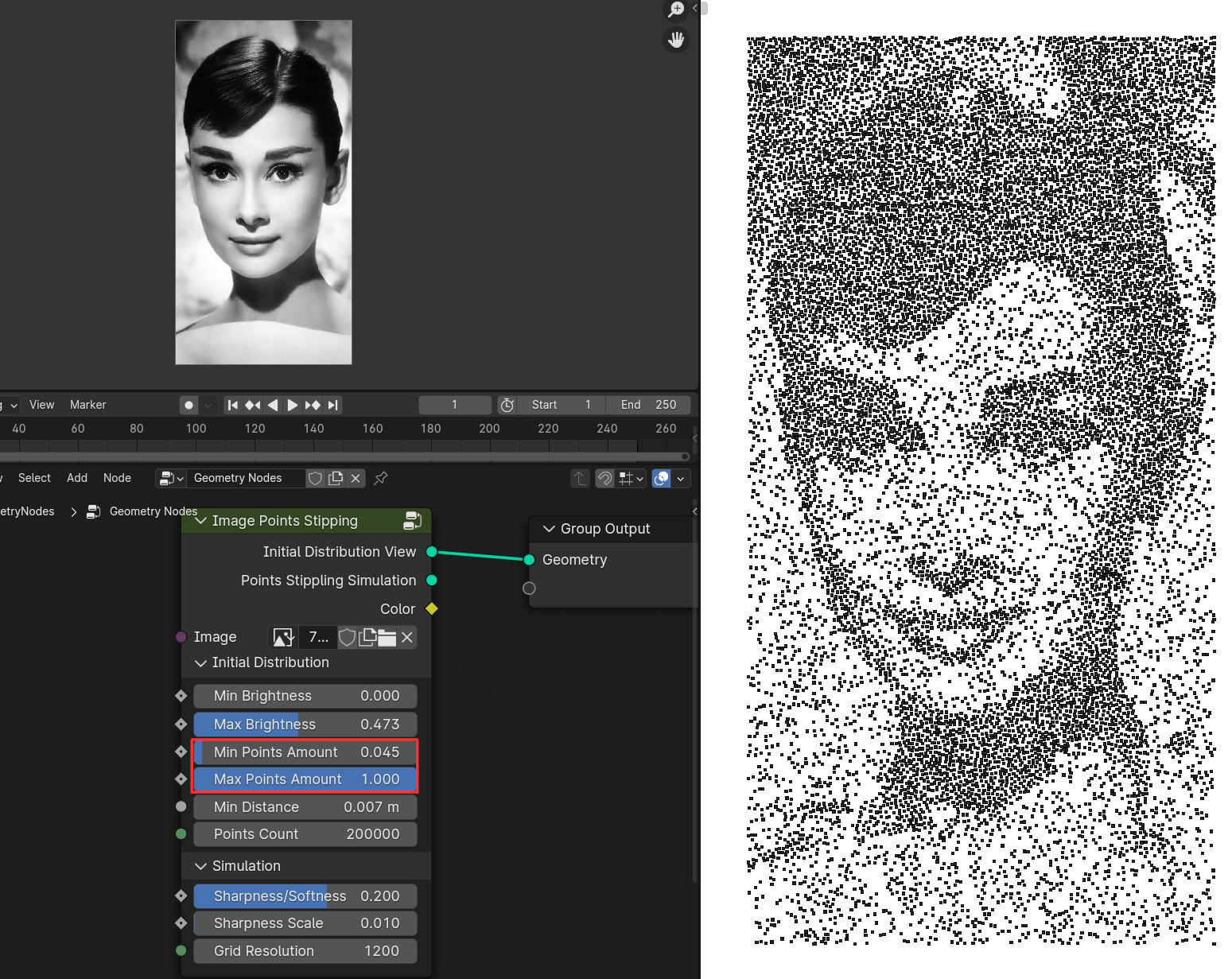
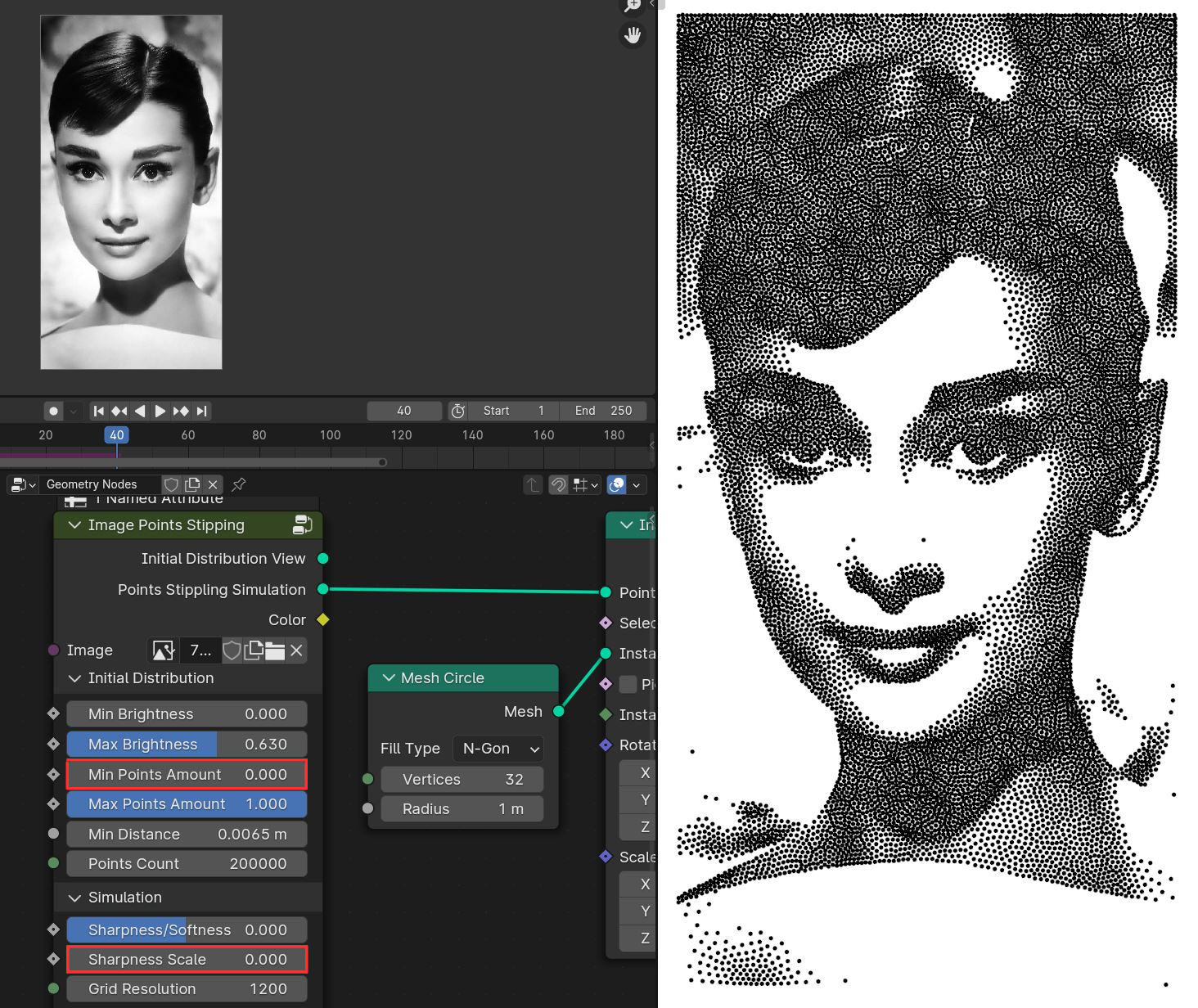
Min Points Amount and Max Points Amount controls density of points for bright and dark portions of the image. For the best results adjust Min Points Amount to get small amount of points in bright areas while keeping image contrast, can leave it to the default. Max Points Amount can be decreased if you have too many points in dark areas, preferably leave it default of 1
Min Distance controls density in the dark areas, lower values will results in more points in dark areas. Be carefull not to set value too low, resulting in way too many points that will slow simulation significantly. For decent results aim total point count somewhere between 10k / 30k
Points Count initial points count that points will be deleted using image brightness values. Preferably leave it to the default and only increase it, if in some areas points are too sparse
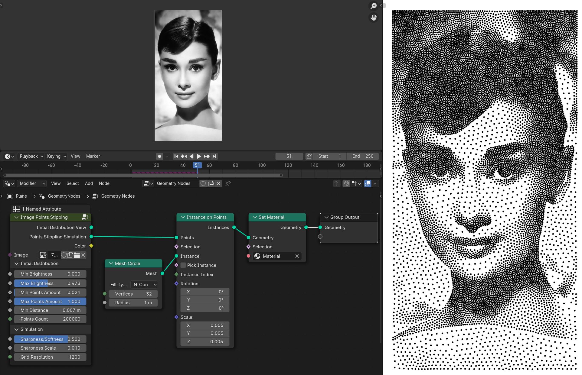
Simulation
After adjusted Initial Distribution settings, connect Points Stippling Simulation to the Group Output and rund the simulation
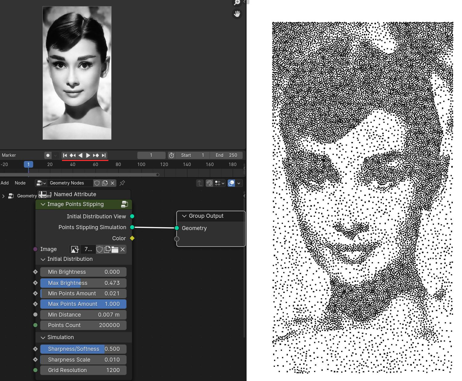
Usually it will take about 50 frames to get good stippling effect
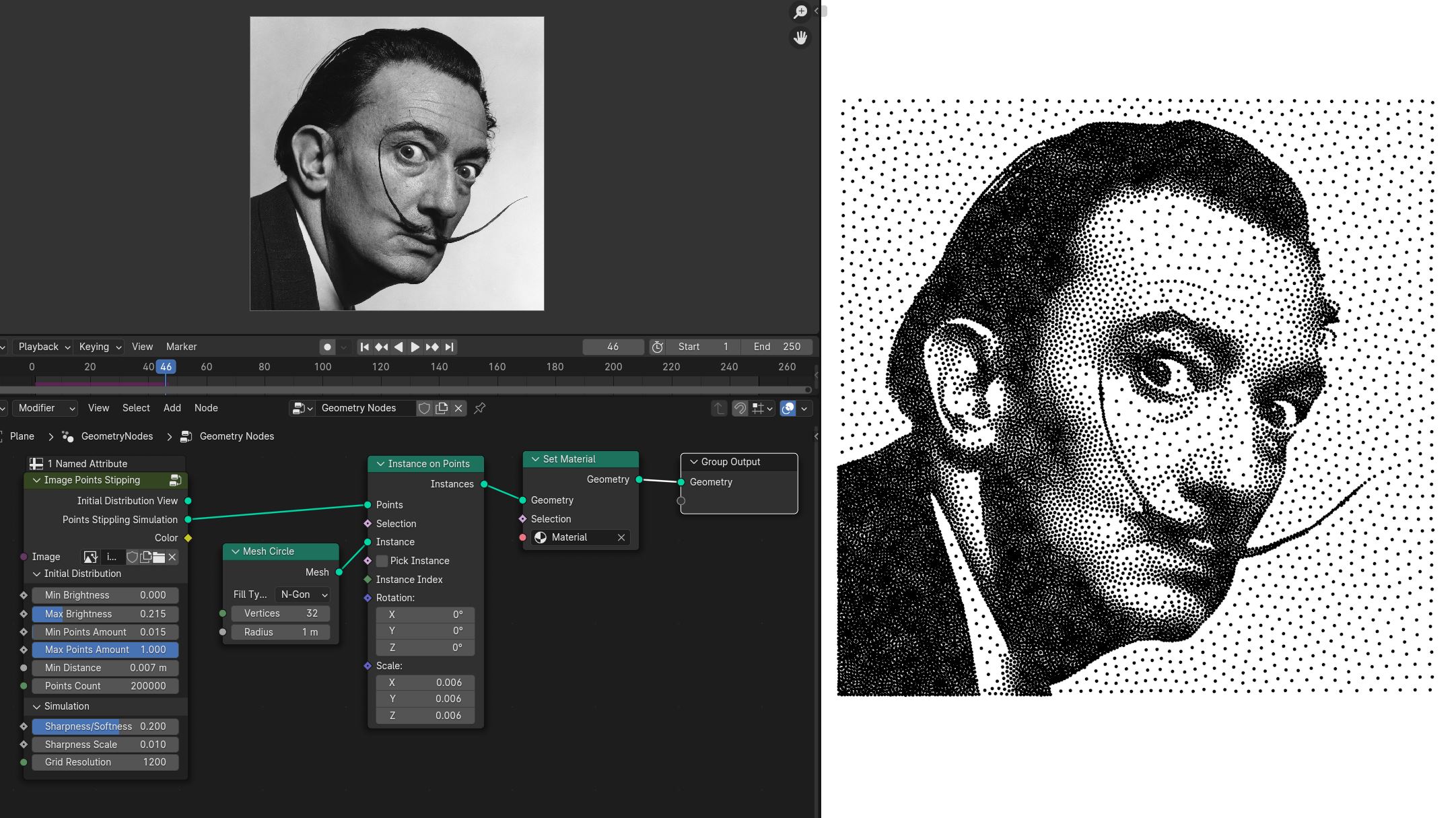
Instancing spheres on to points with small radius
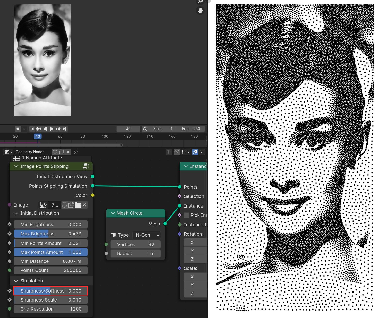
Sharpness/Softness controls the gradient of the points distribution, negatives values will results in sharper gradient cut off, positives values results in softer gradient. Preferably use the values in between 0 and 1
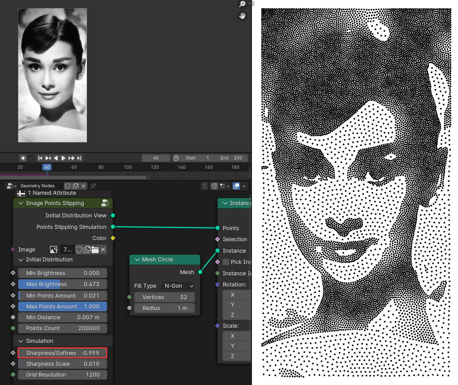
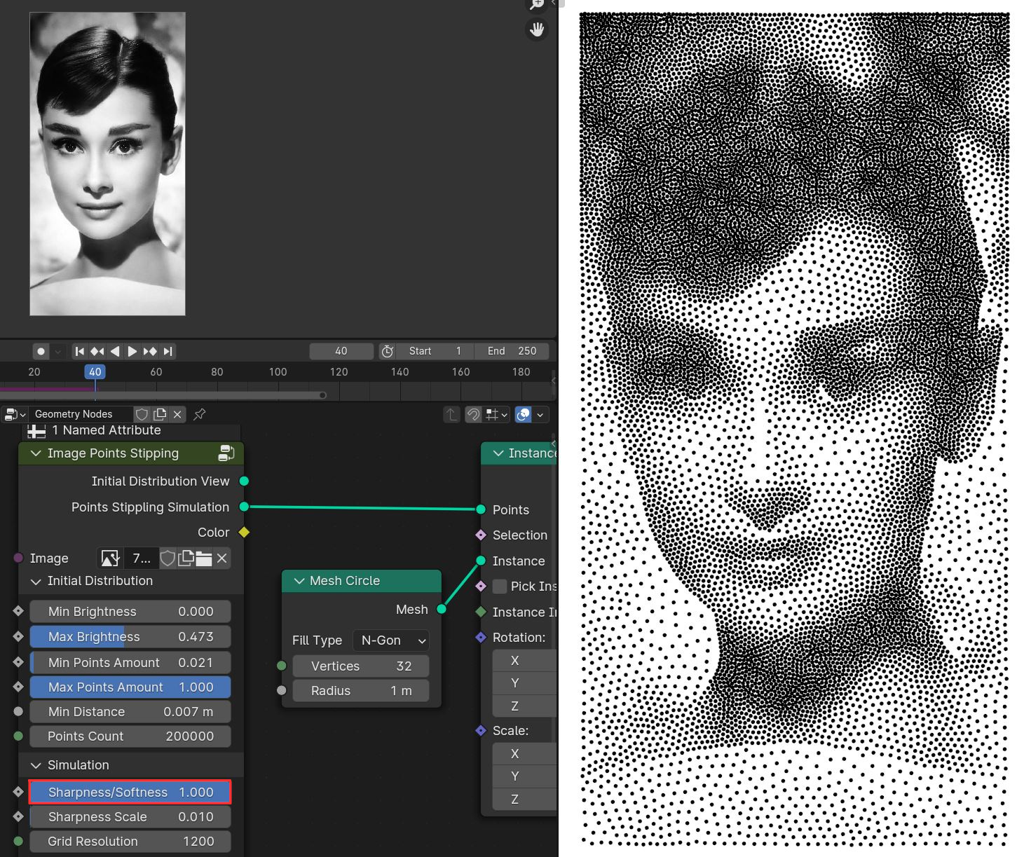
Sharpness Scale controls gradient difference between bright and dark ares. If set Sharpness Scale to 0, points in bright ares will not apear. Leave it default value 0.01
Grid Resolution used to calculate weighted voronoi coordinates for points directions to move. For better quality of points distribution, grid resolution can be increased. Make sure keep it around 1200 / 2000 or higher grid resolution will make simulation significantly slower
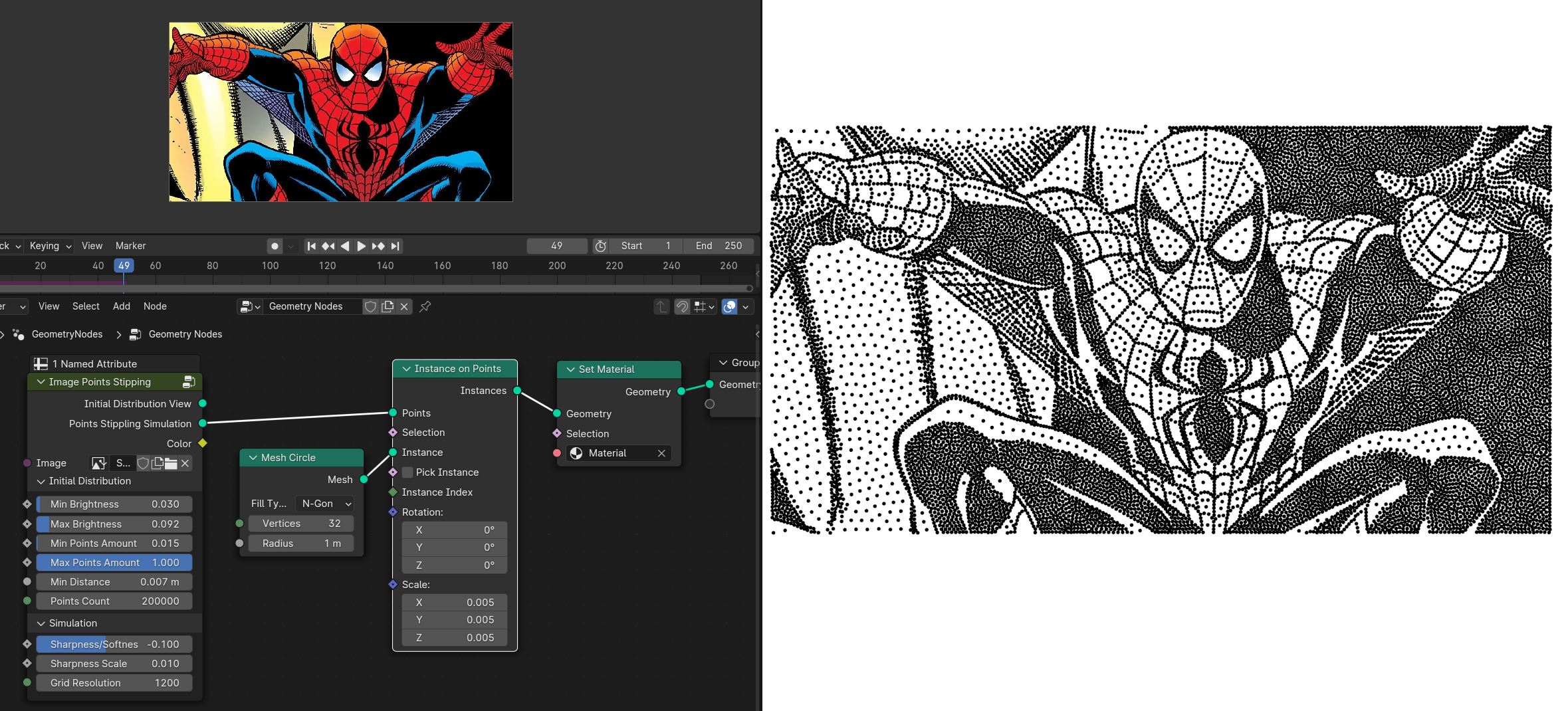
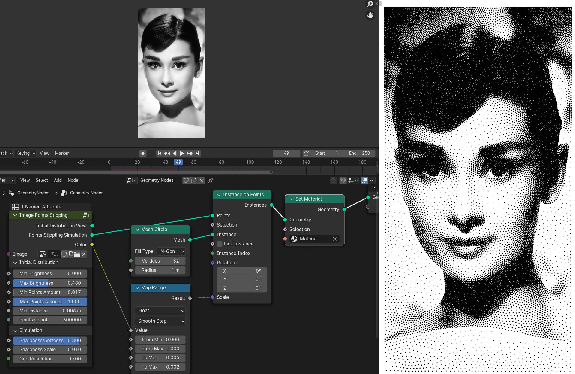
Color attribute can be use for controlling points scale from image texture for better effect
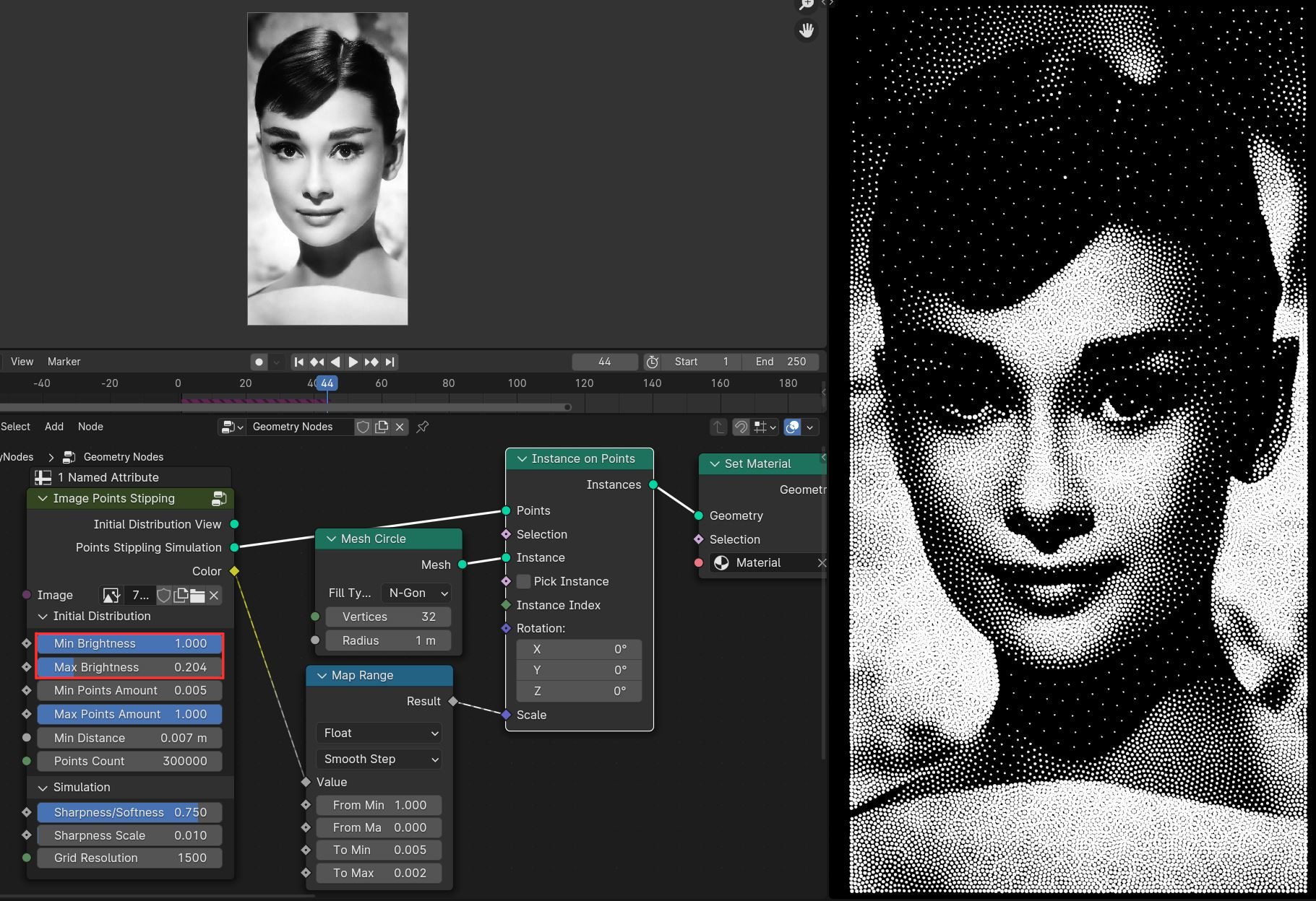
Stippling effect can be inverted by inverting Min Brightness and Max Brightness values
To apply the simulation, apply geo nodes modifier with realized circle instances, or convert points to vertices by using Points to Vertices nodes and apply the geo nodes modifier
Tip
You can use fill curve trick to convert points to triangular mesh
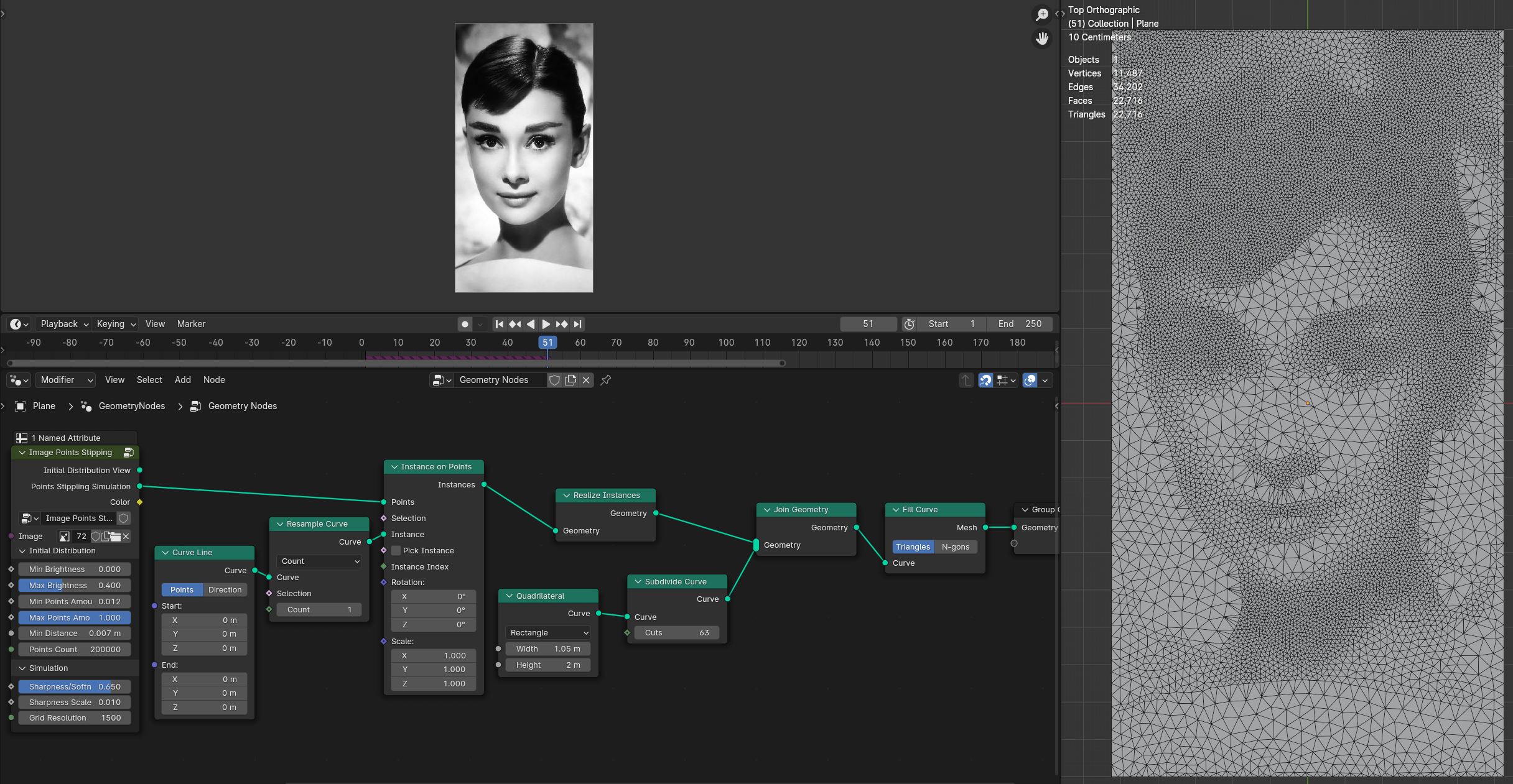
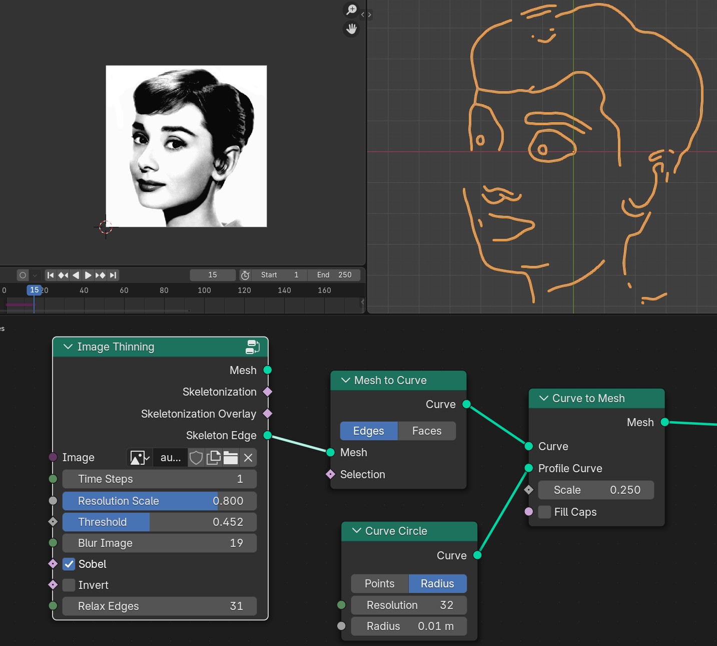
Image Thinning
Calculates image Straight Skeleton lines
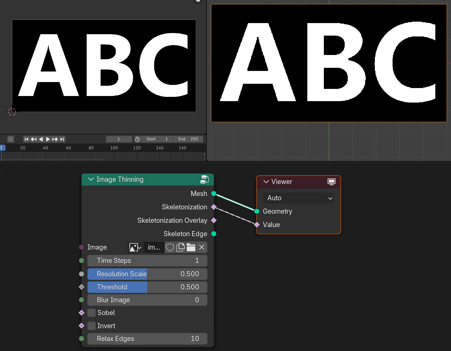
- Times Steps
Times steps of the simulation
- Resolution Scale
Grid resolution scale from image pixels
- Threshold
Threshold that image will be converted to white and black pixels
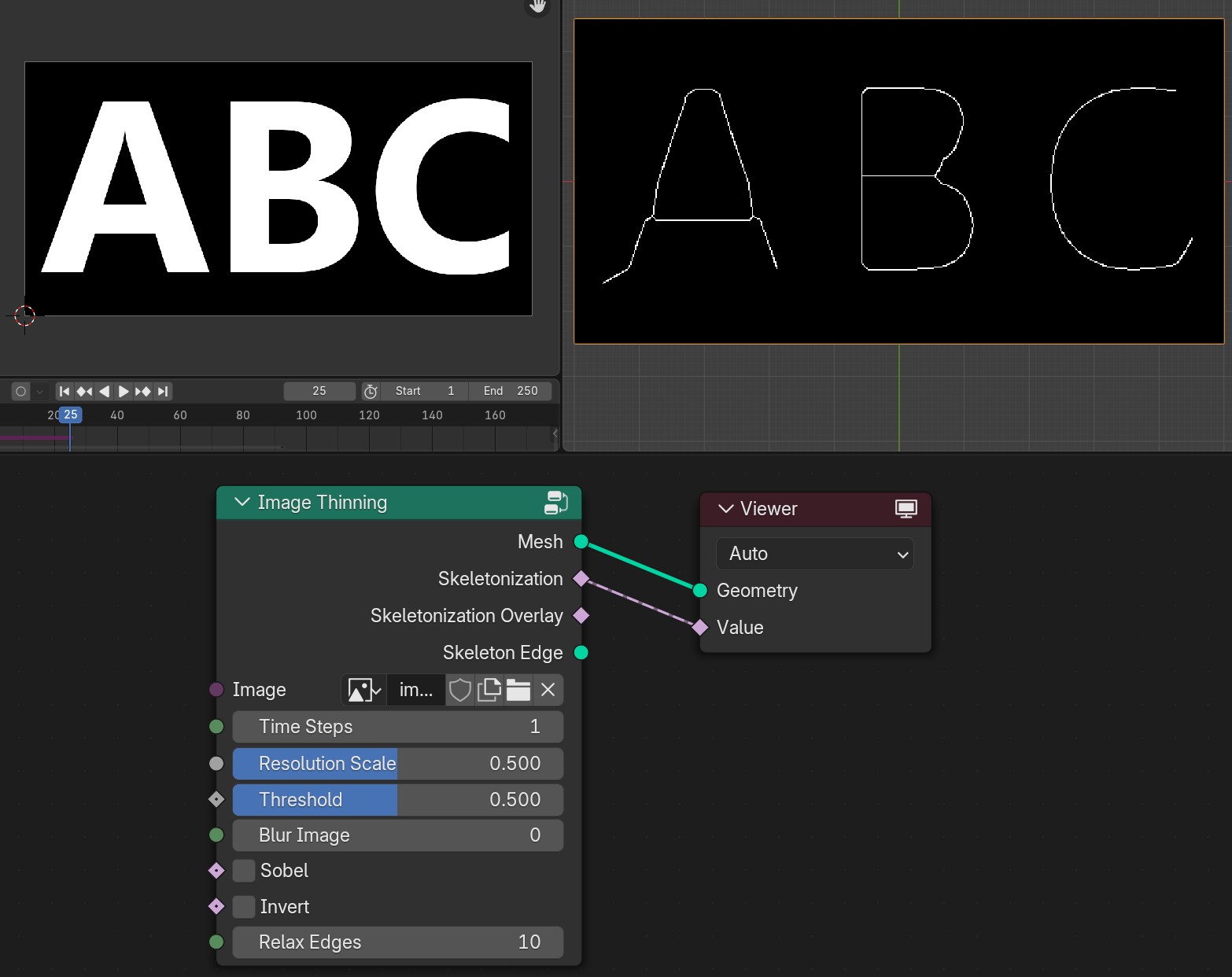
- Blur Image
Blurs Image
- Sobel
Will extracts image edges
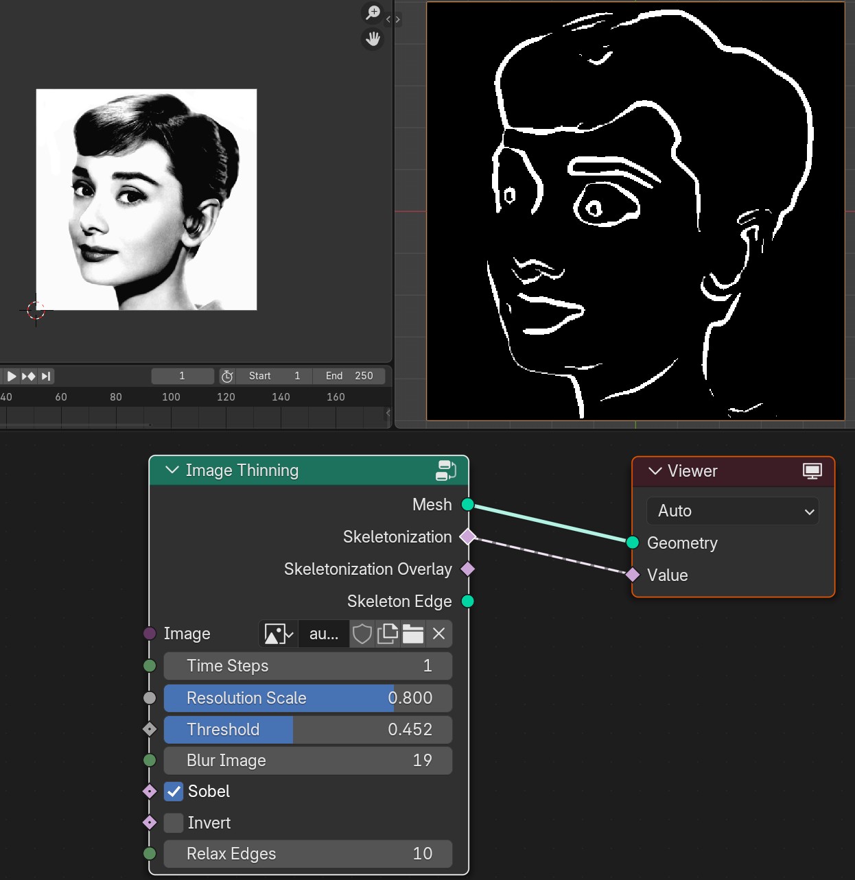
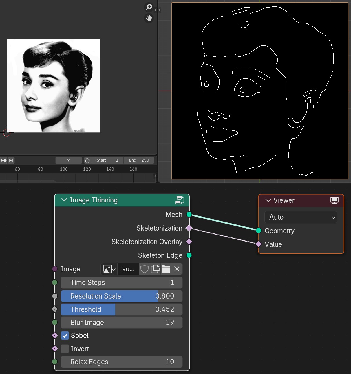
- Invert
Inverts values
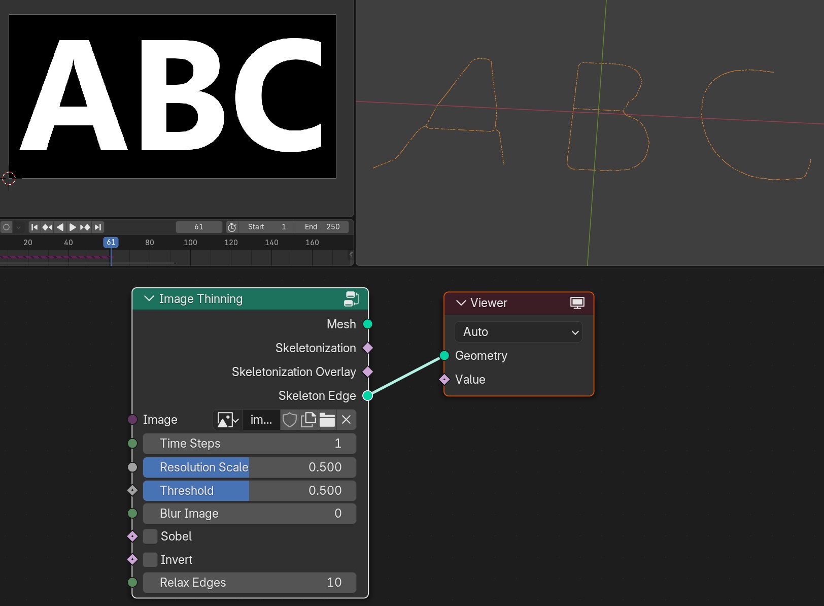
- Relax Ddges
Relaxes edges extracted from image straight skeleton
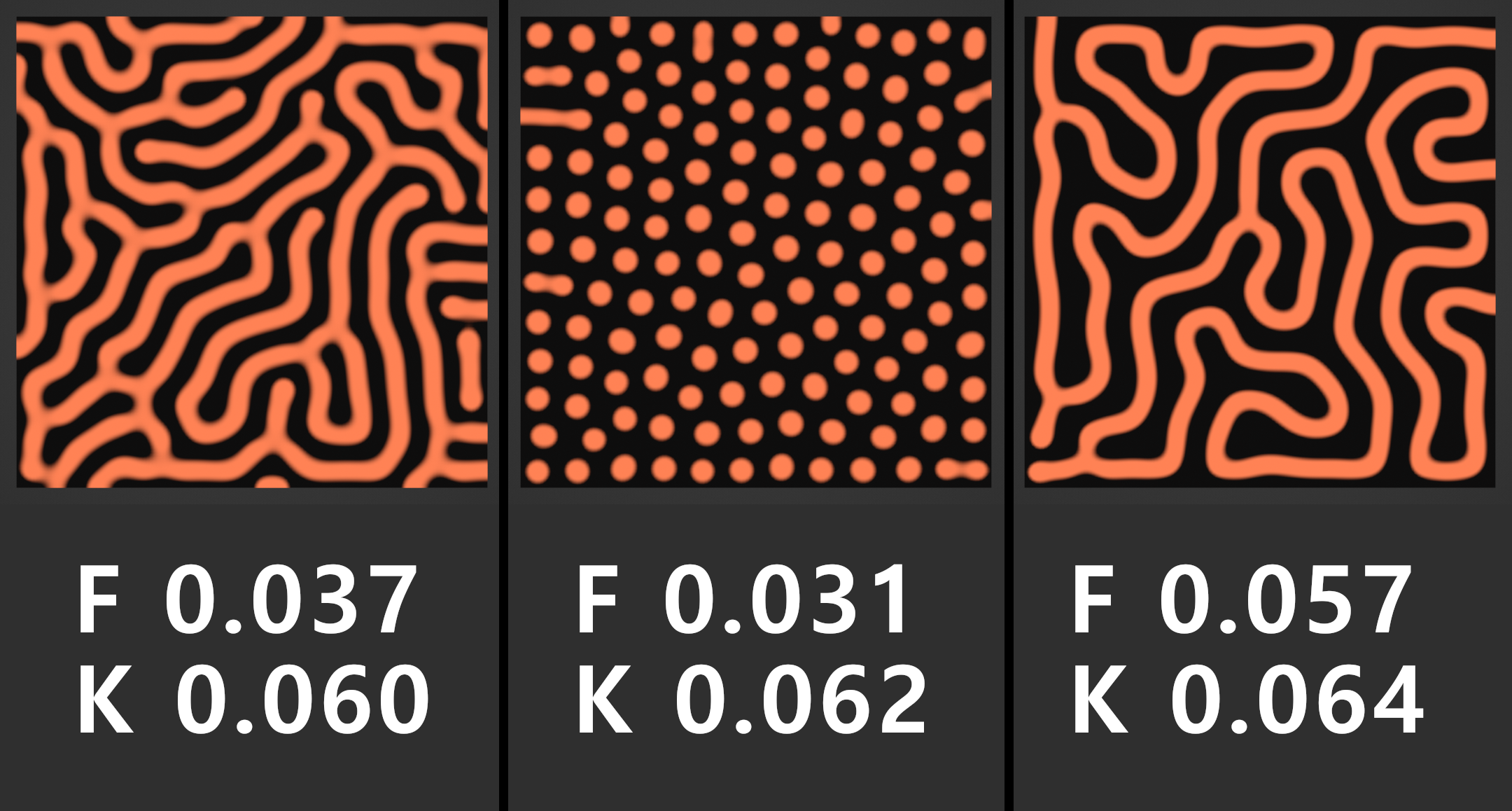
Reaction Diffusion Solver
Creates growing/mixing effect between two virtual chemicals
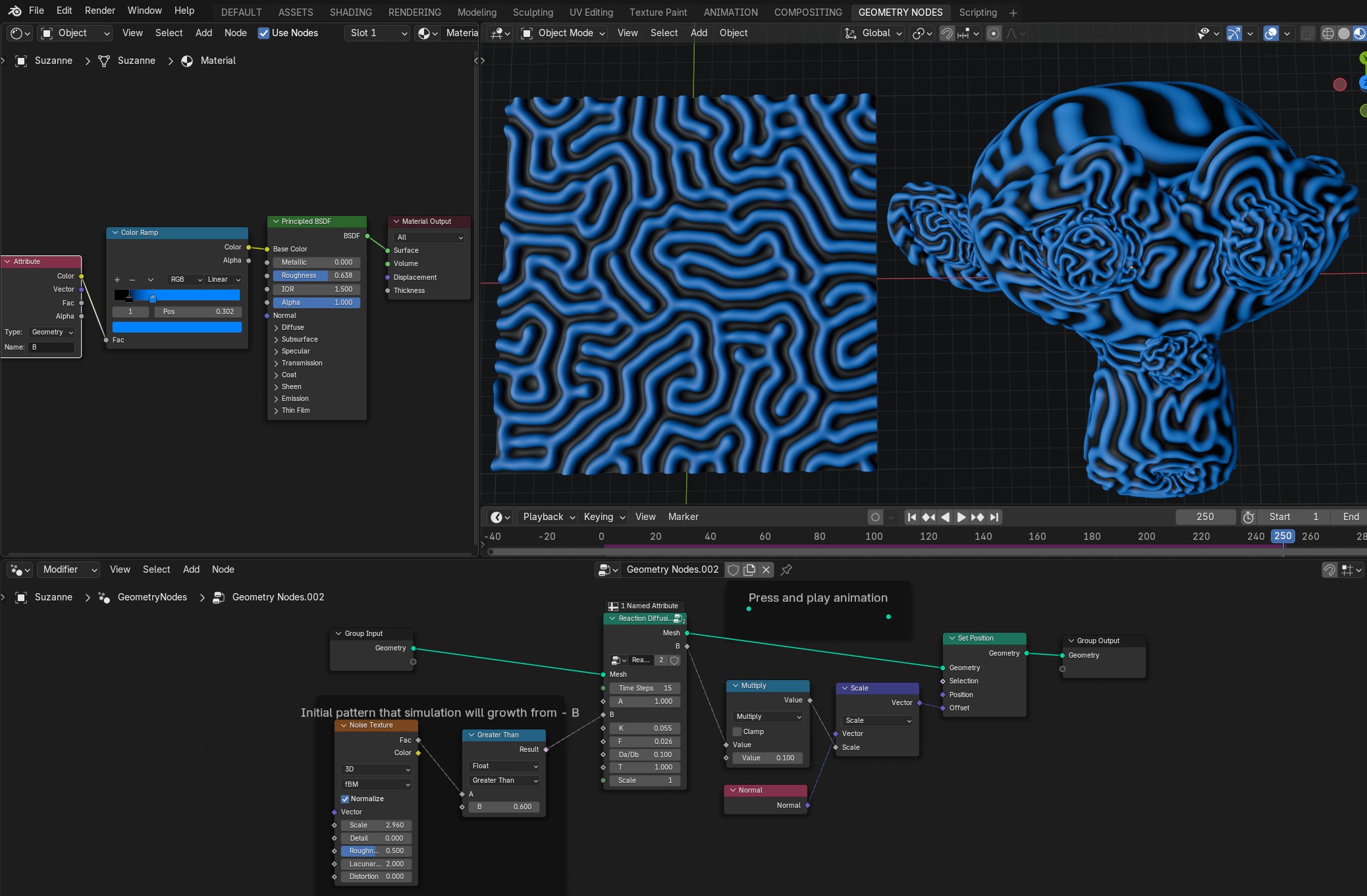
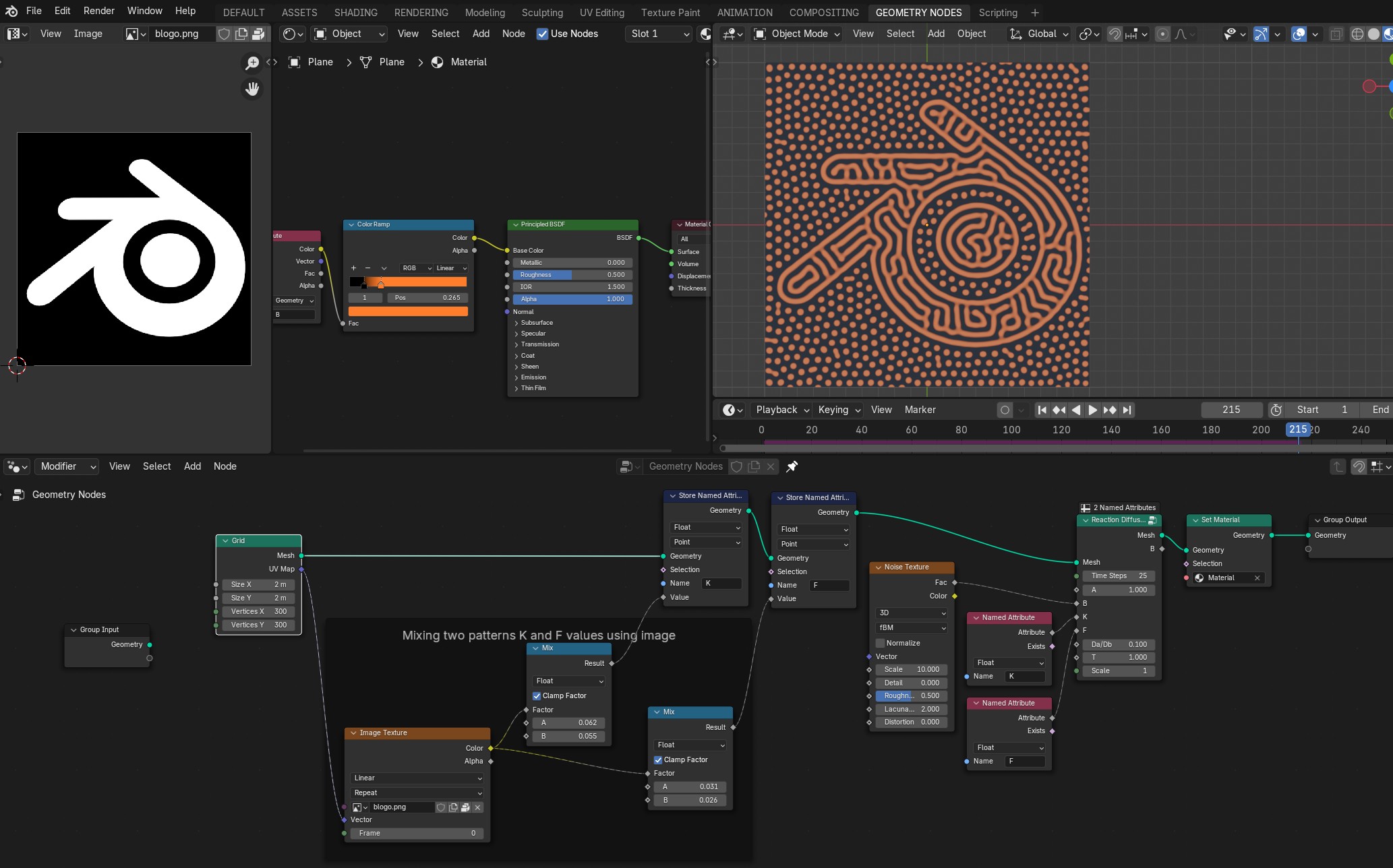
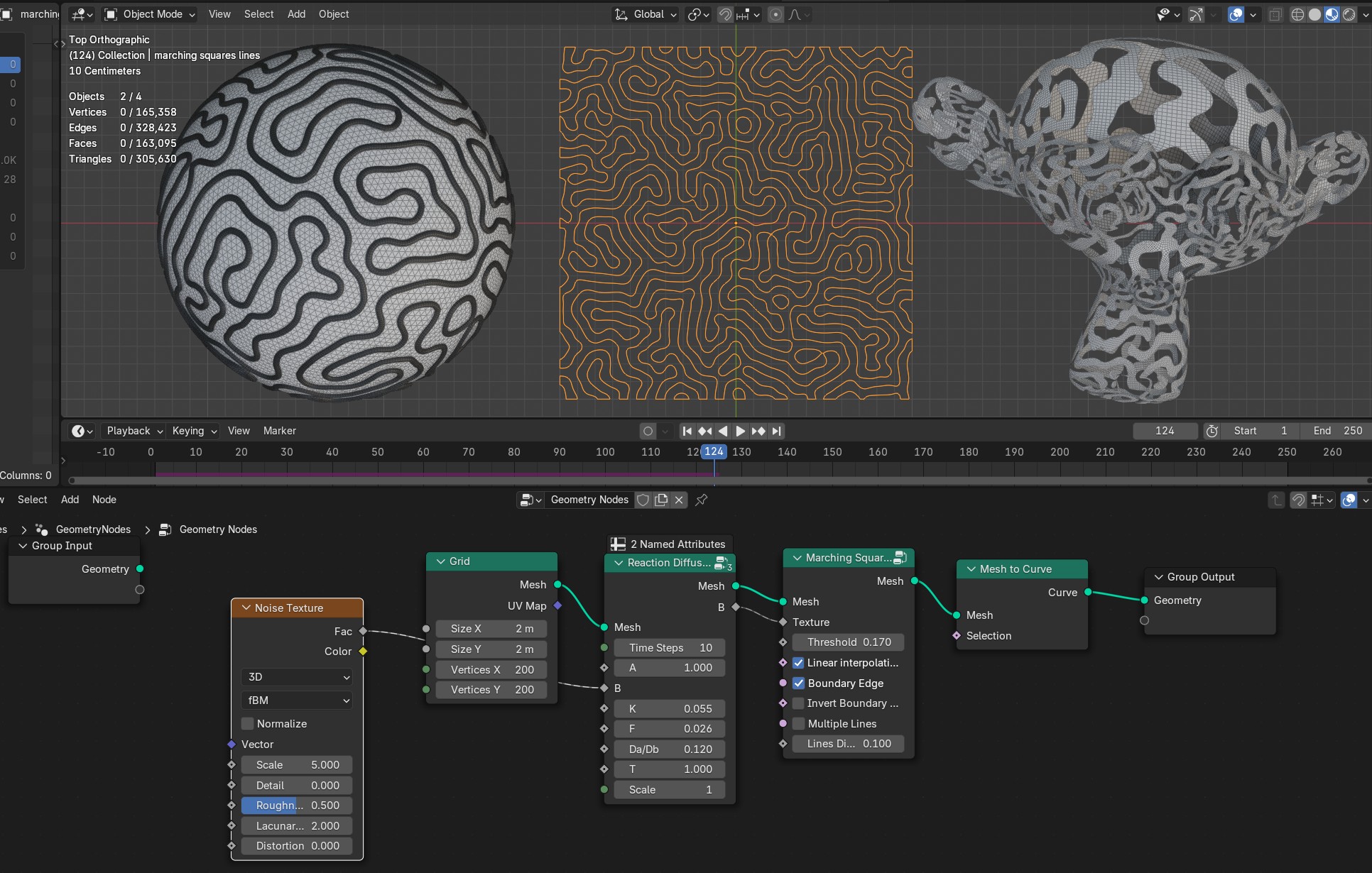
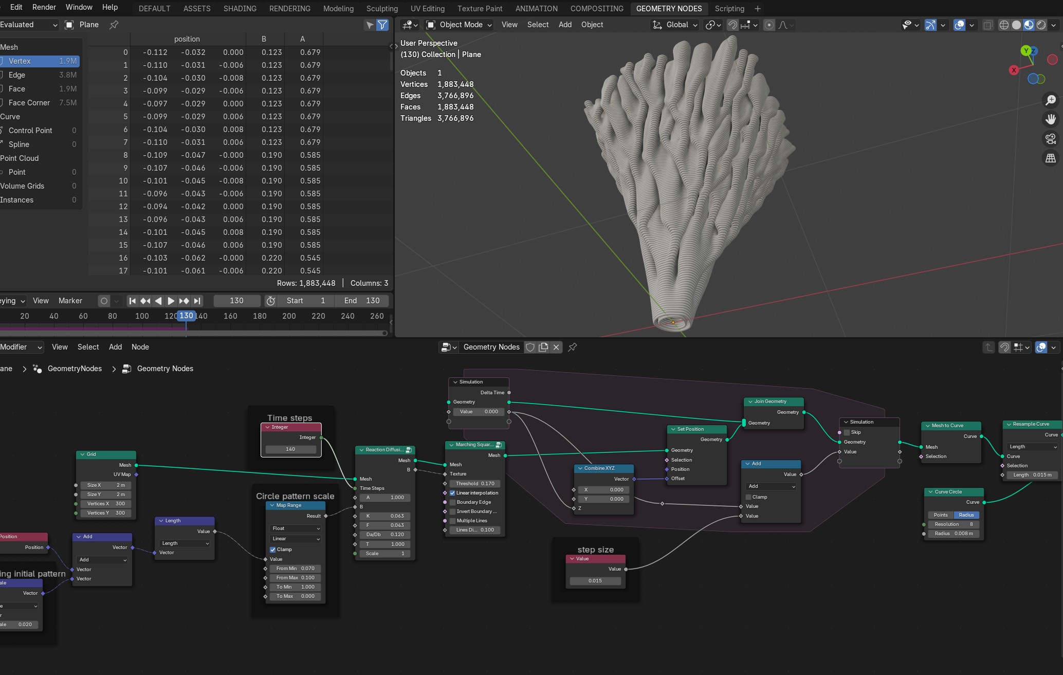
- A
Chemical A value stored on the mesh (set to 1)
- B
Chemical B value stored on the mesh (set it to some random texture/noise that effect will growth from)
- F
Chemicals feed rate
- K
Chemicals kill rate
Example F and K values

- T
Time scale of the simulation (going above 1.5 simulation will become unstable)
- Scale
Scale of the grouth pattern
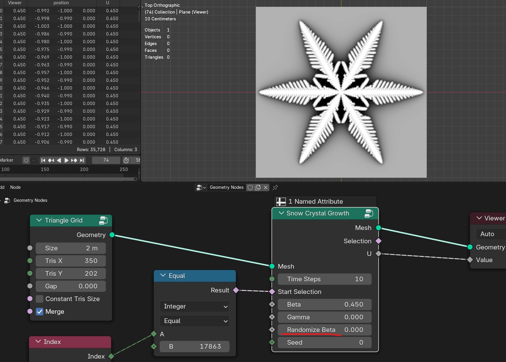
Snow Crystal Growth
Simulates snow crystal growth from starting vertex selection
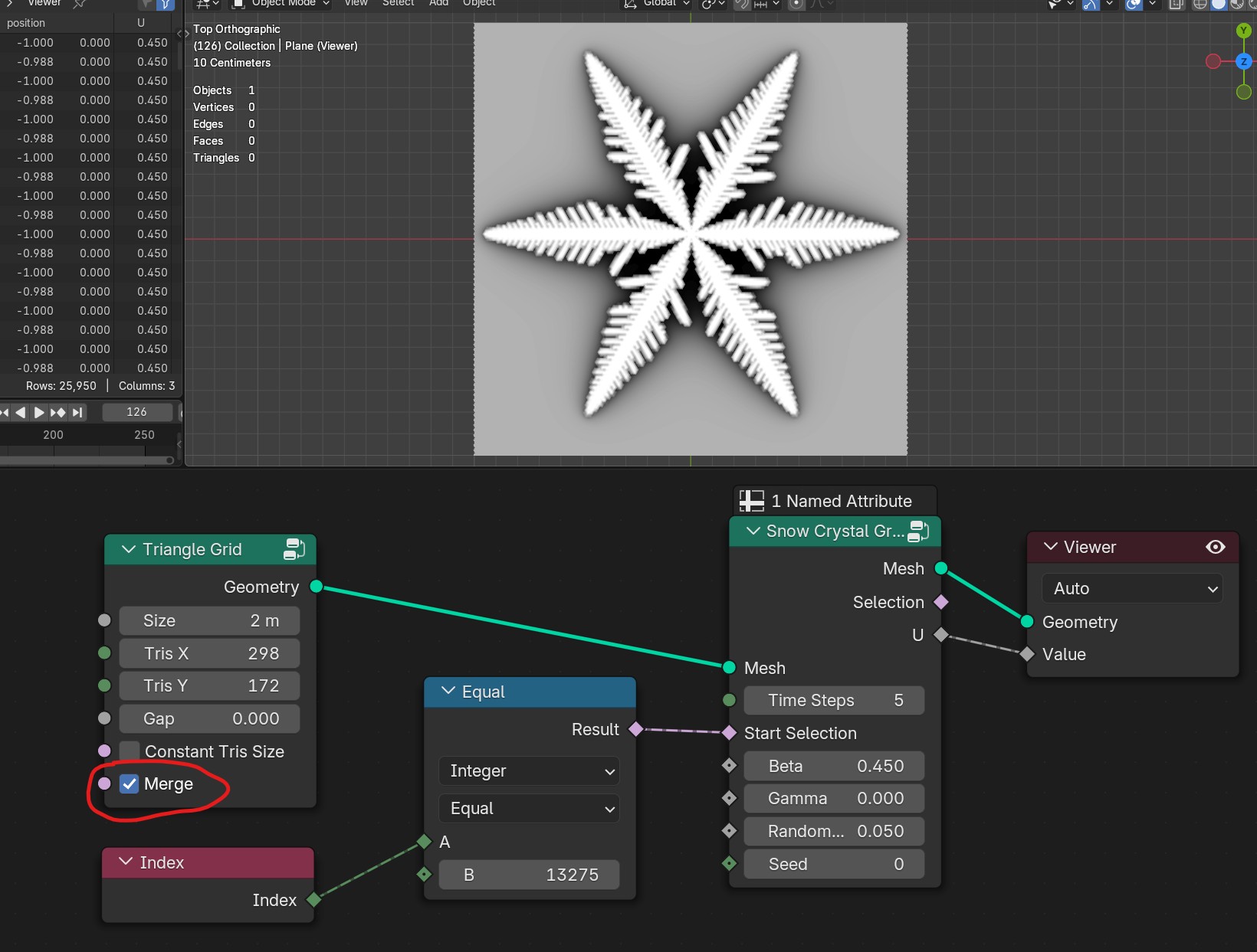

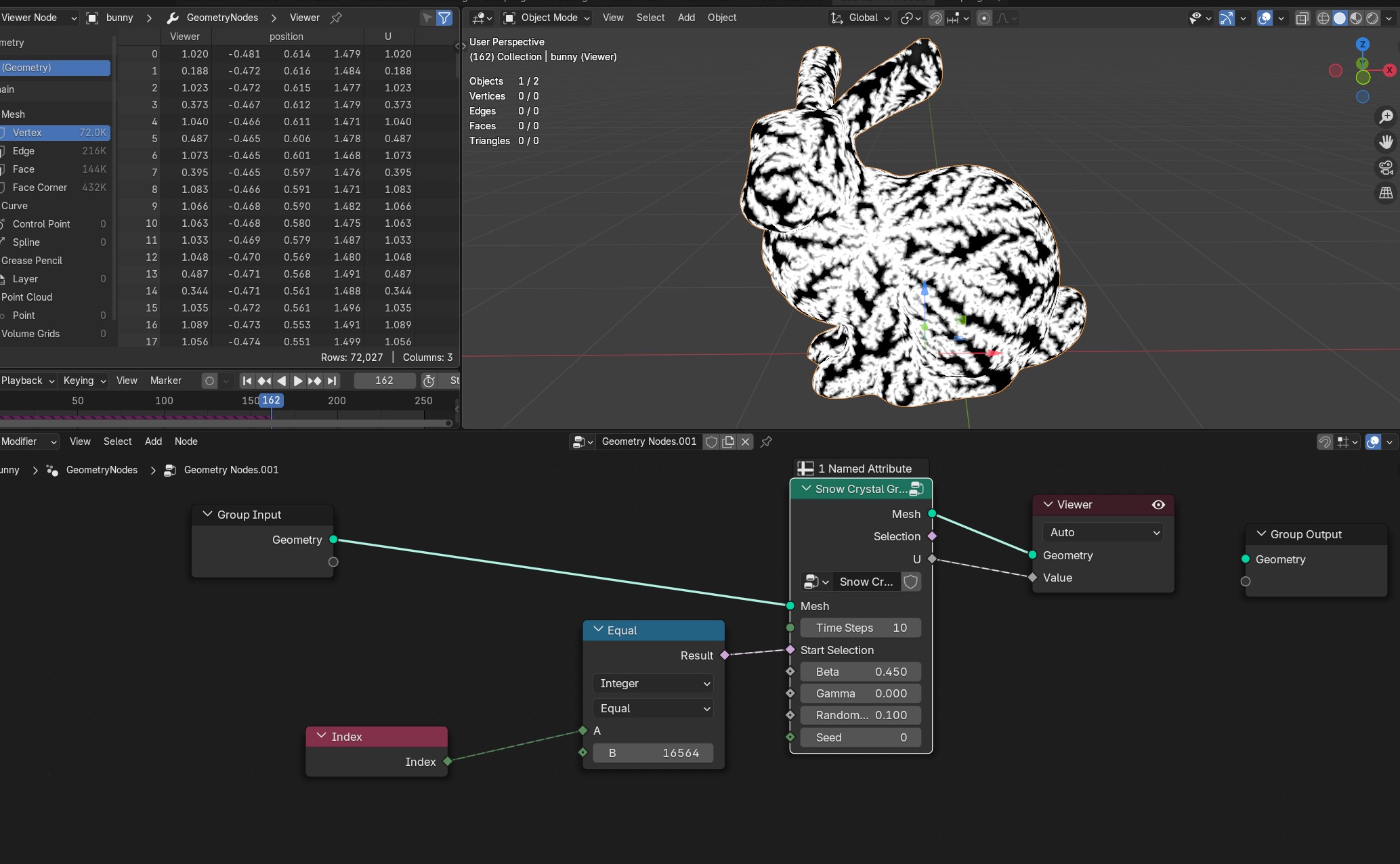
- Time Steps
Number of simulation steps per frame
- Start Selection
Start vertex selection that snow crystal will grow from
- Beta
Parameter of the simulation
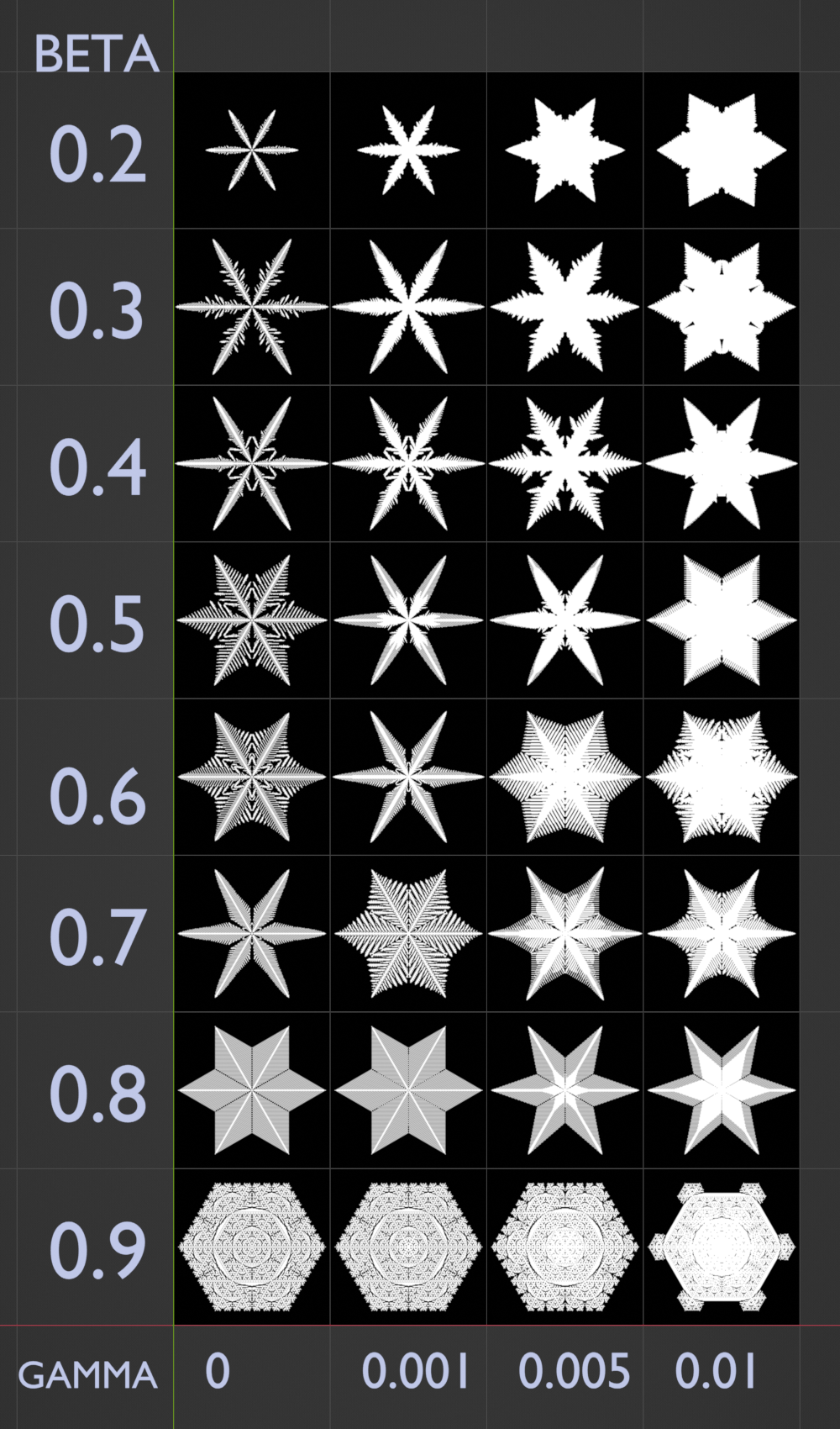
- Gamma
Parameter of the simulation
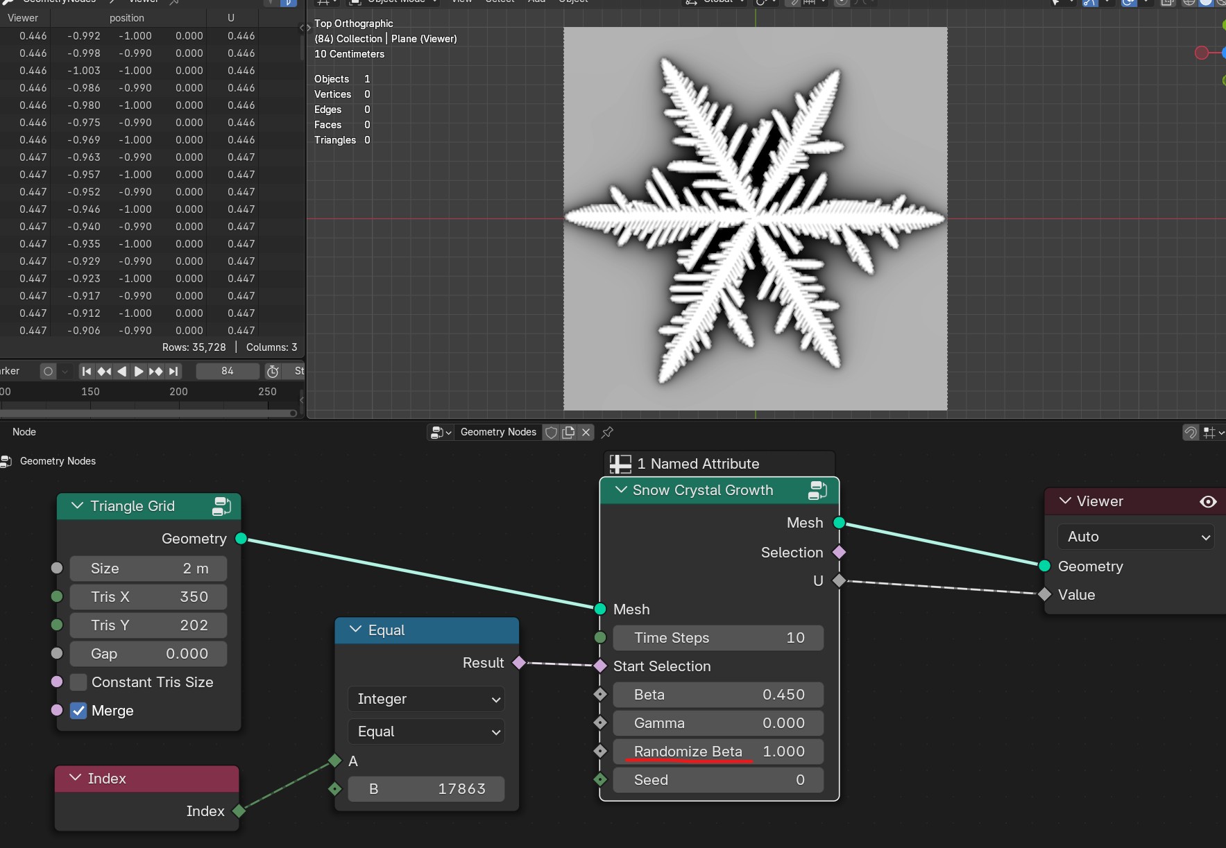
- Randomize Beta
Randomizes beta parameter
- Seed
Seed of randomization
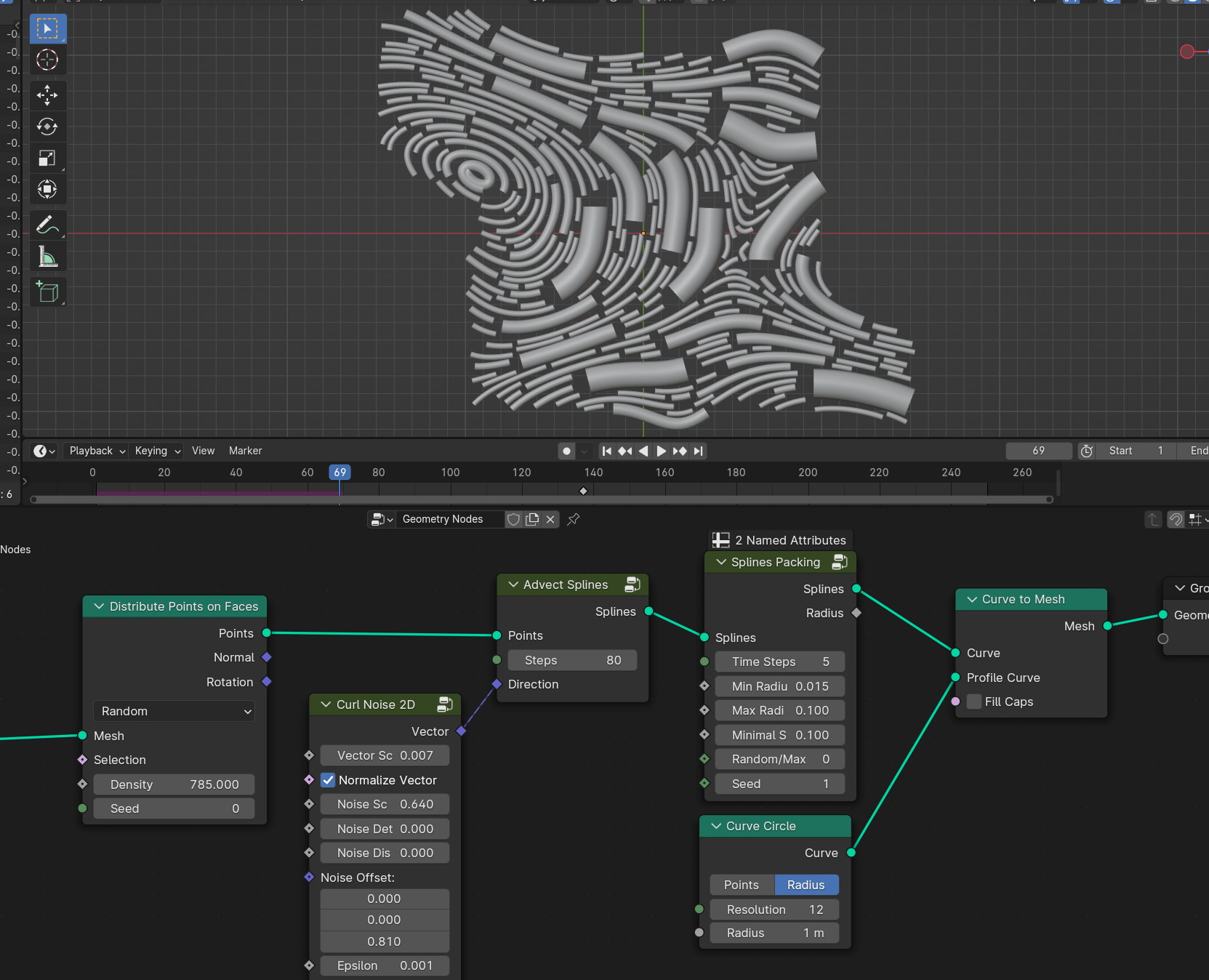
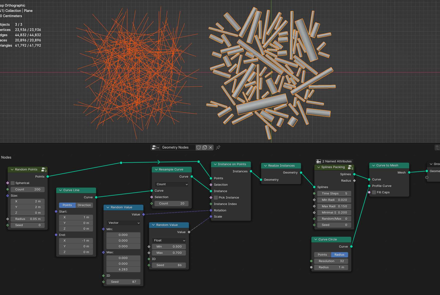
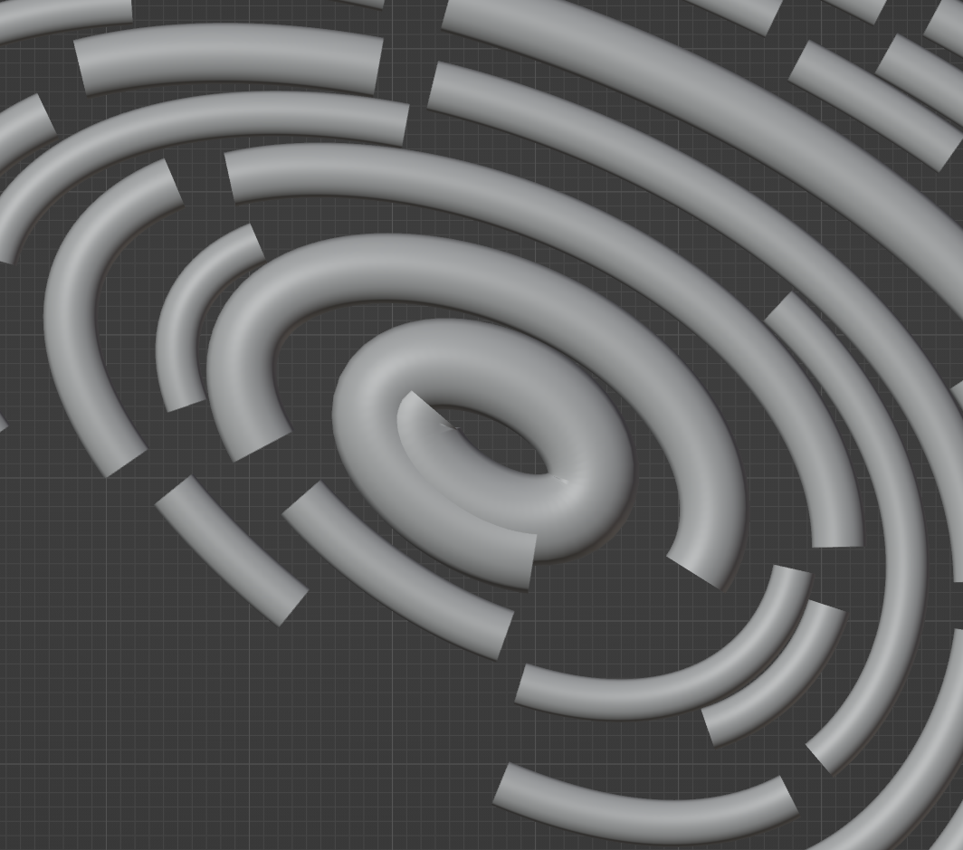
Splines Packing
Removes overlaping splines each simulation step
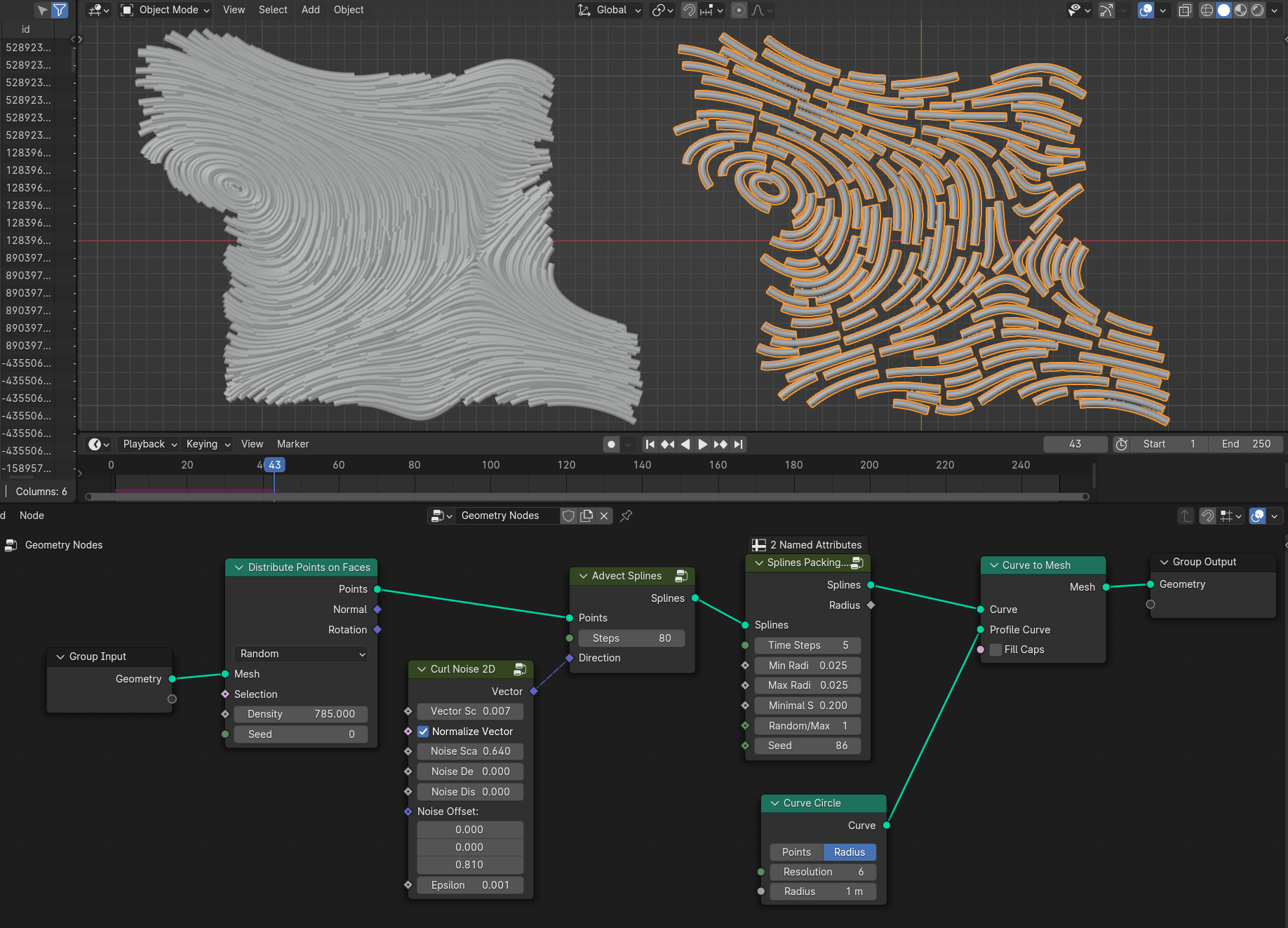
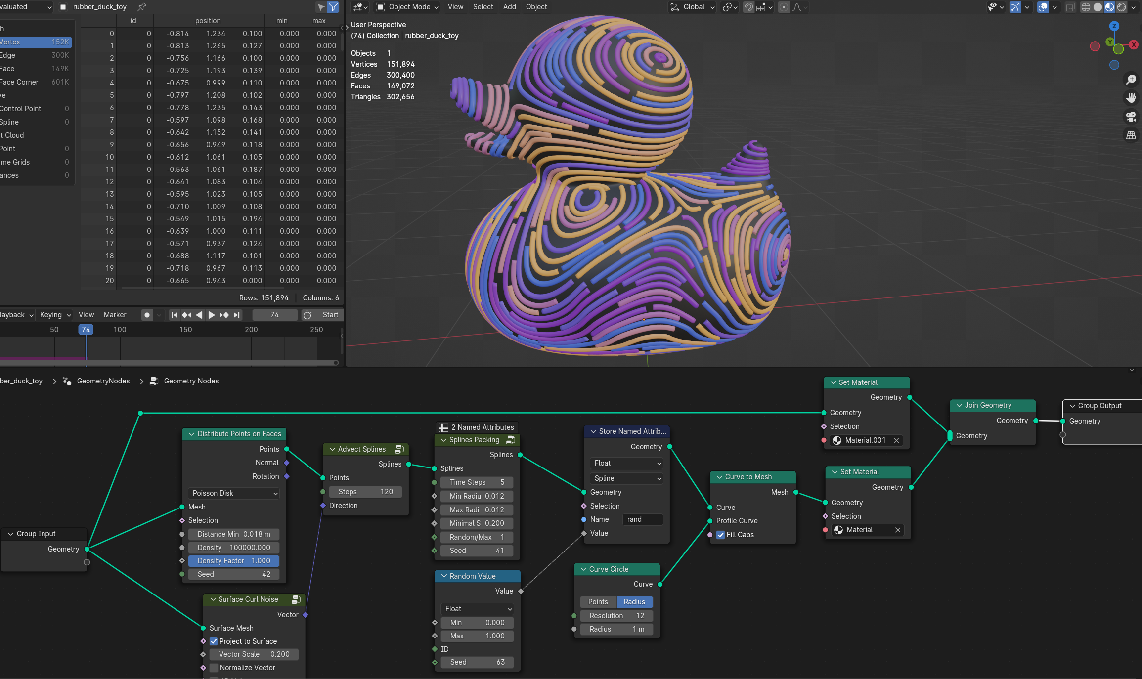
- Time Steps
Number of simulation steps per frame
- Min Radius
Min radius of the splines
- Max Radius
Max radius of the splines
- Minimal Splines Length
Removes splines with mininal distance
Random/Max Radius
Random Each interation sets spline radius to random value, and will clamp it with existing splines that it won’t overlap. It will give more randomized radius, but with bigger gaps
Max Radius Each interation sets splines radius to max radius to the closest existing splines. It will result in tighter gaps between splines but with more uniform radius
- Seed
Seed of setting random radius between min and max
Warning
Splines can be overlaping with itself
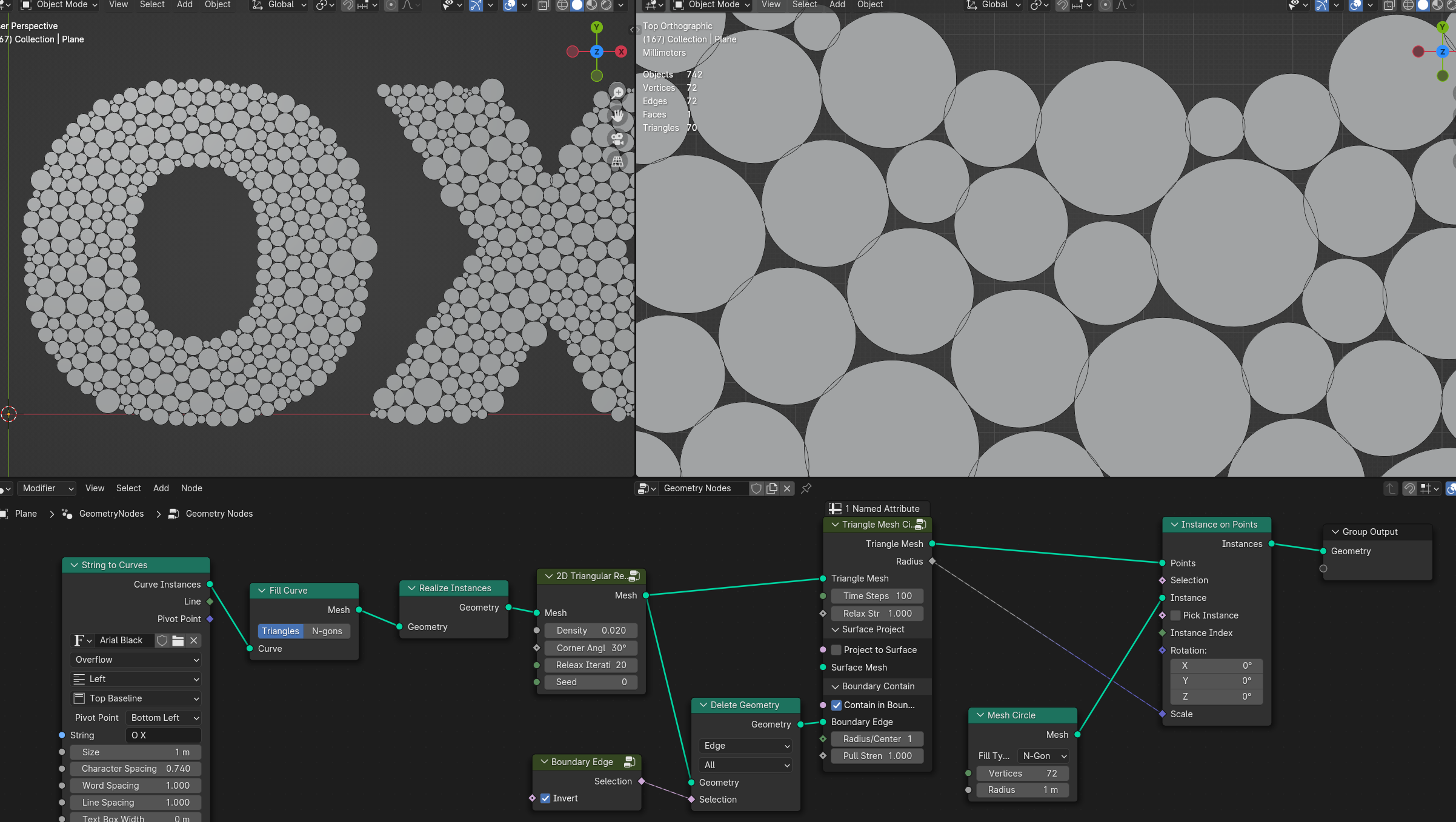
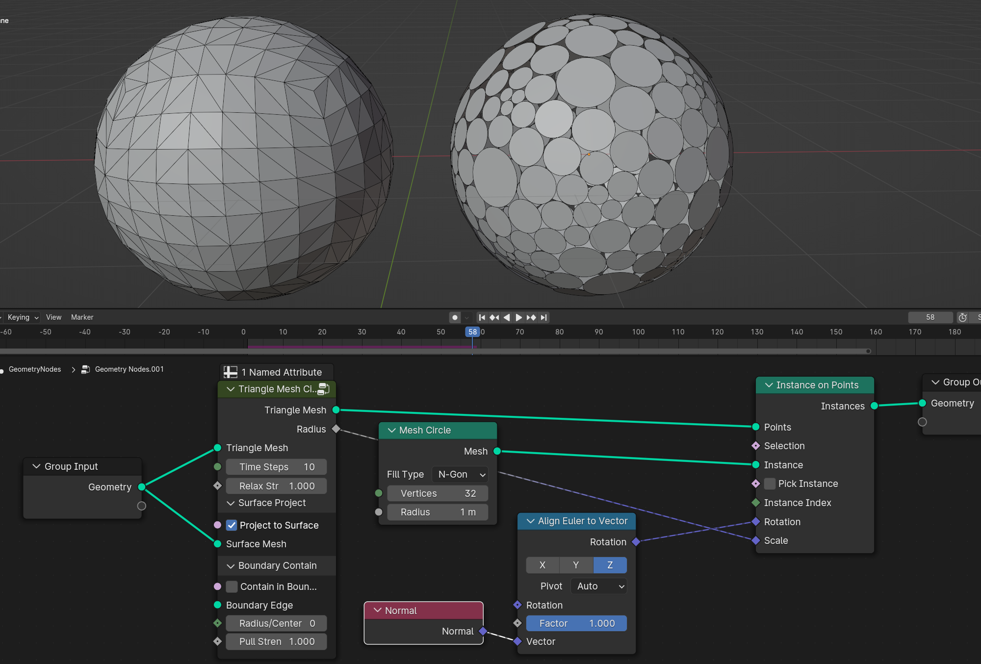
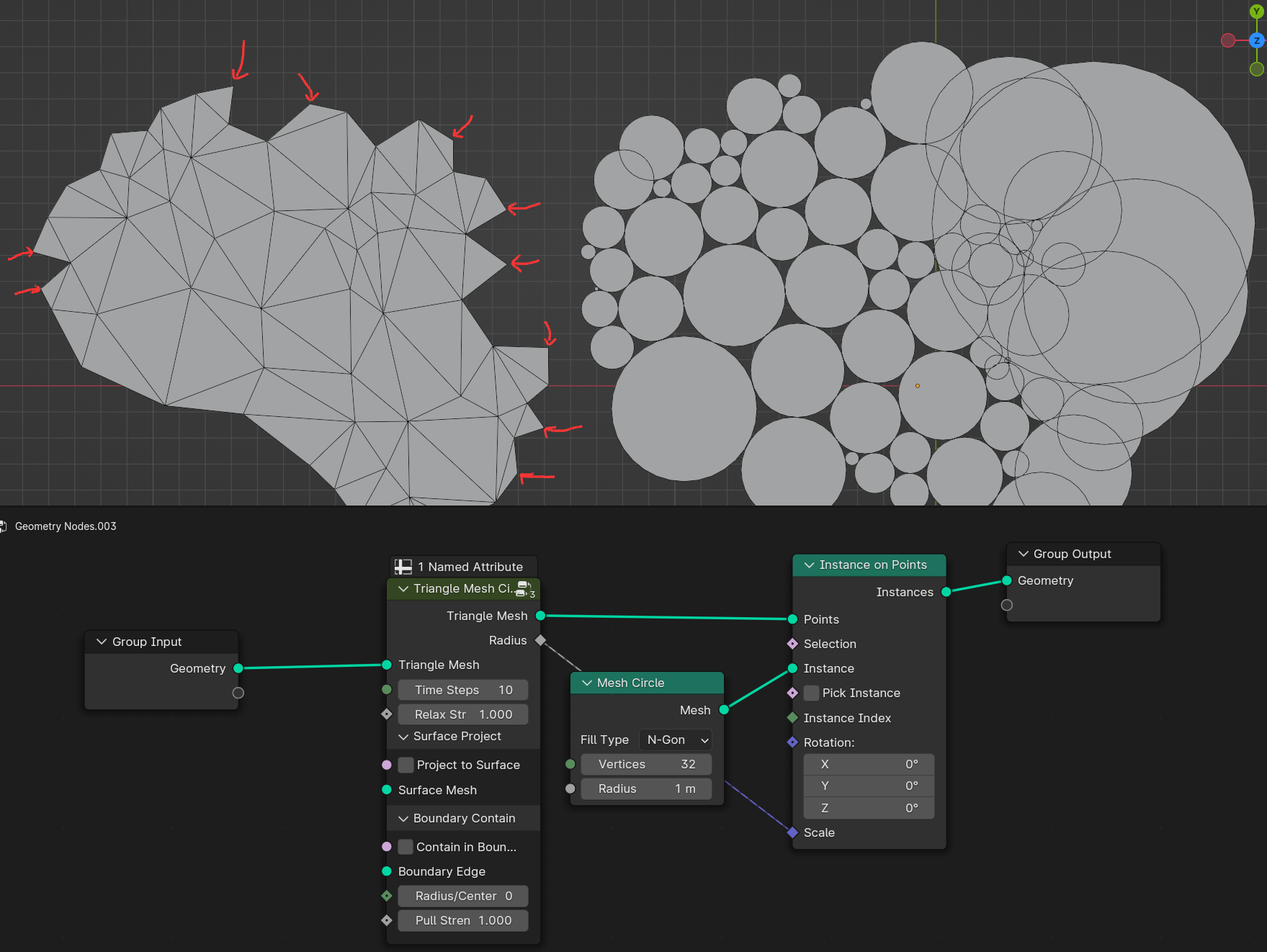
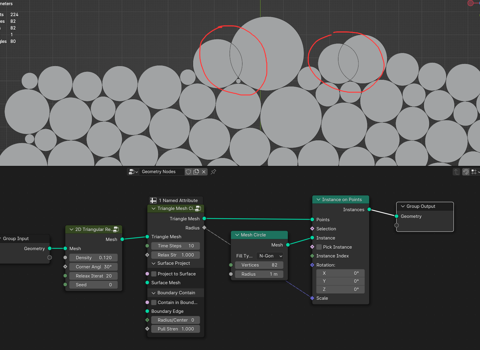
Triangle Mesh Circle Packing
Relaxes triangulated mesh to fit tangent circles using simulation
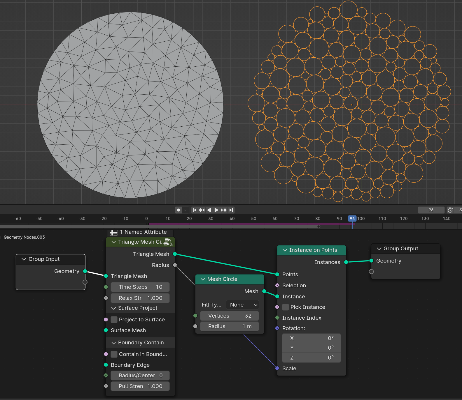
- Time Steps
Number of simulation steps per frame
- Relax Strenght
The amount of relaxation per step. Going above 1 can create unstable simulation. Value bellow 1 will slow down the simulation for more stable relaxations, but it slow down convergence for circle packing. Preferably leave at 1
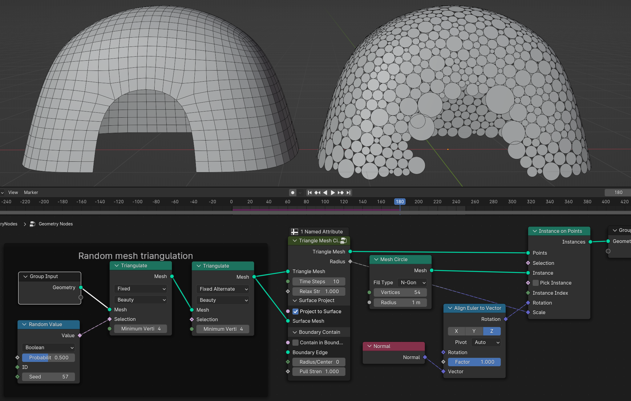
- Project to Surface
Will shrinkwraps relaxed mesh to input mesh to keep the shape
- Surface Mesh
Surface mesh that triangle mesh will be shrinkwraped
- Contain in Boundary
Tries to contain circles inside the boundary edge
- Boundary Edge
Mesh boundary edge
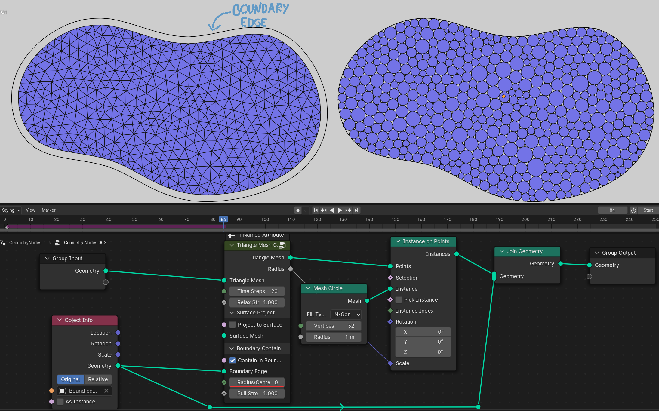
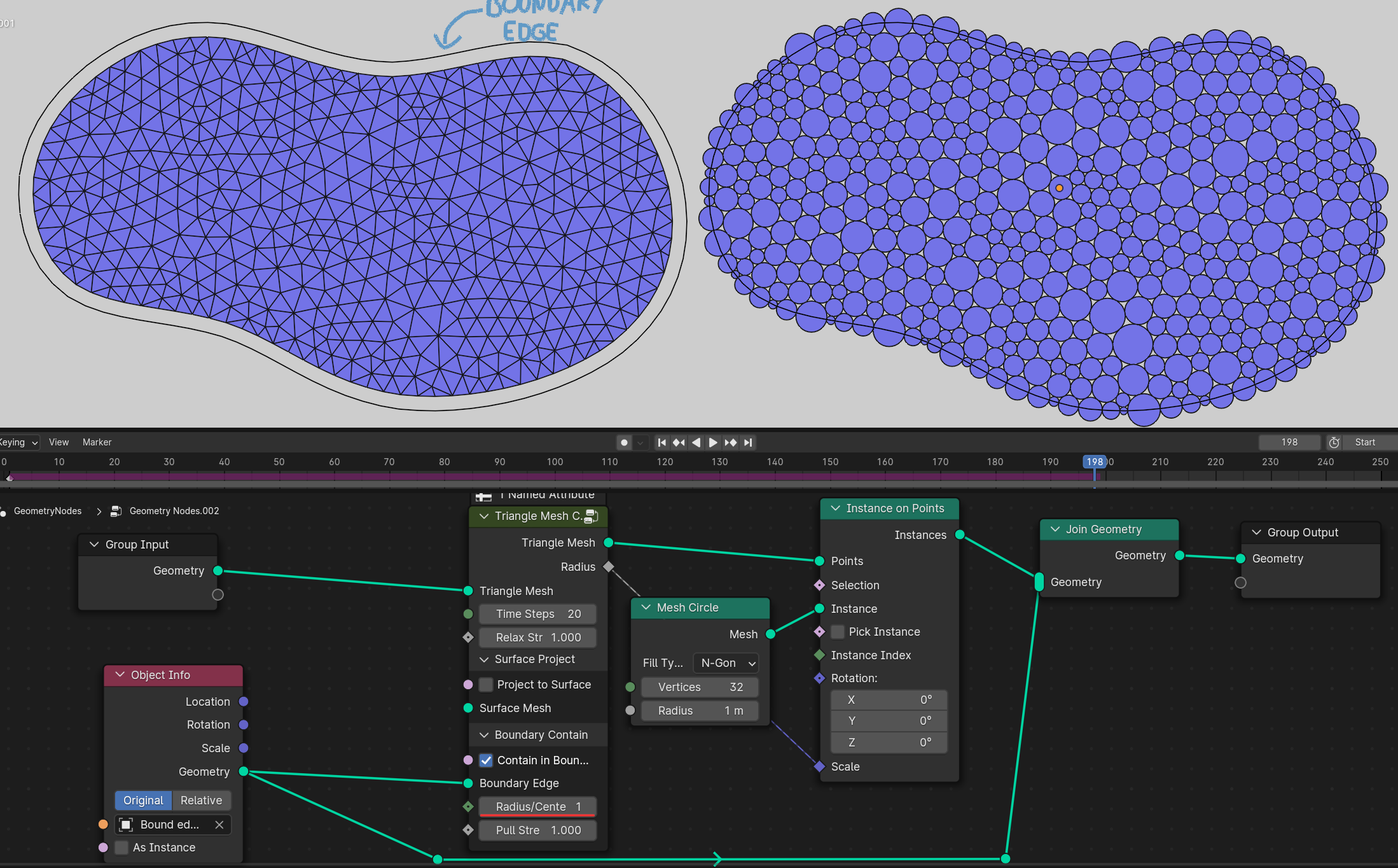
Radius/Center
0 Circles will touch the boundary edge with circle side. Important boundary edge must be some distance offsetted from triangle mesh
1 Circles center will be on the boundary edge
- Pull Strength
Strength for pulling circles to the boundary edge
Using boundary edge on 3d surface
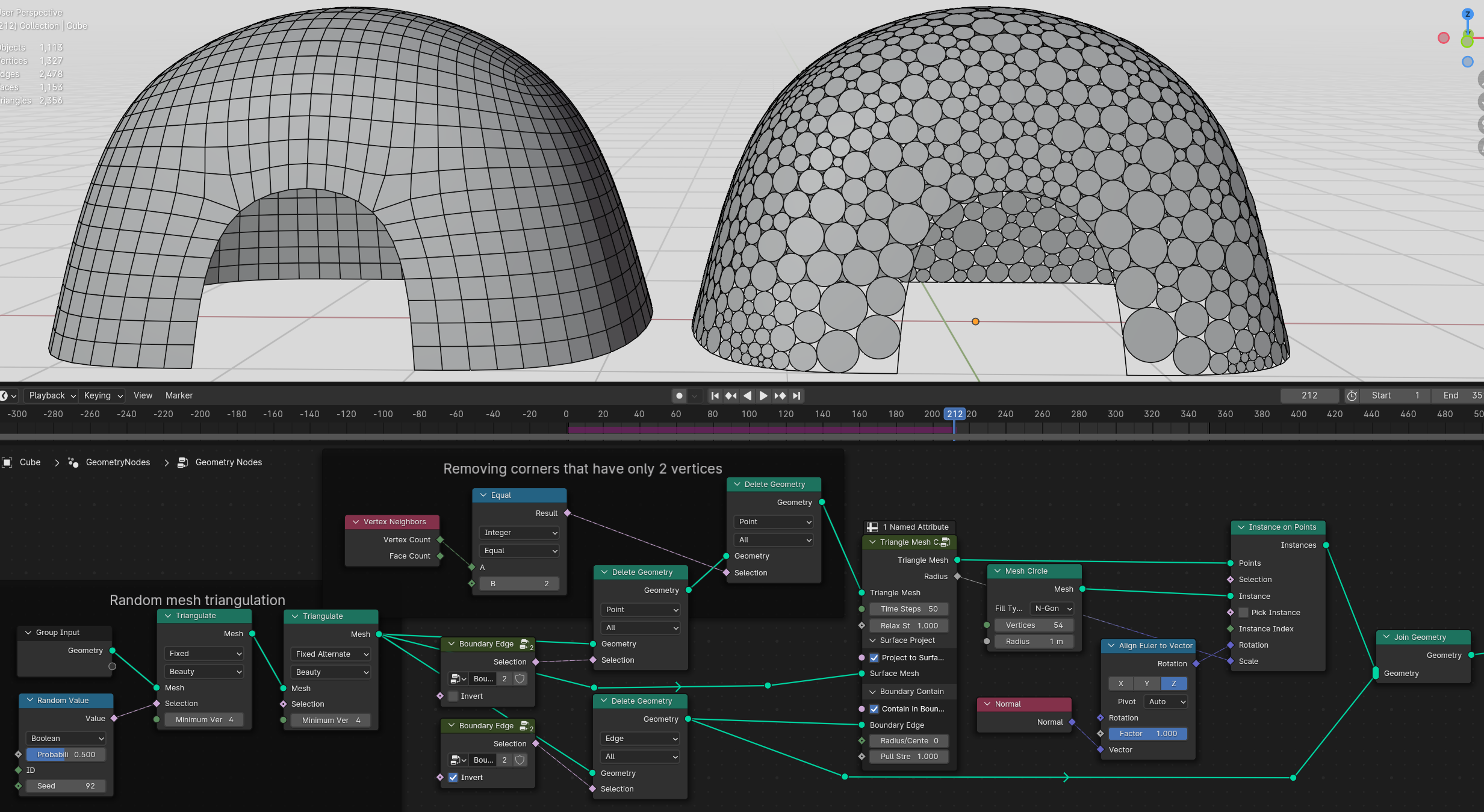
Warning
Limitations
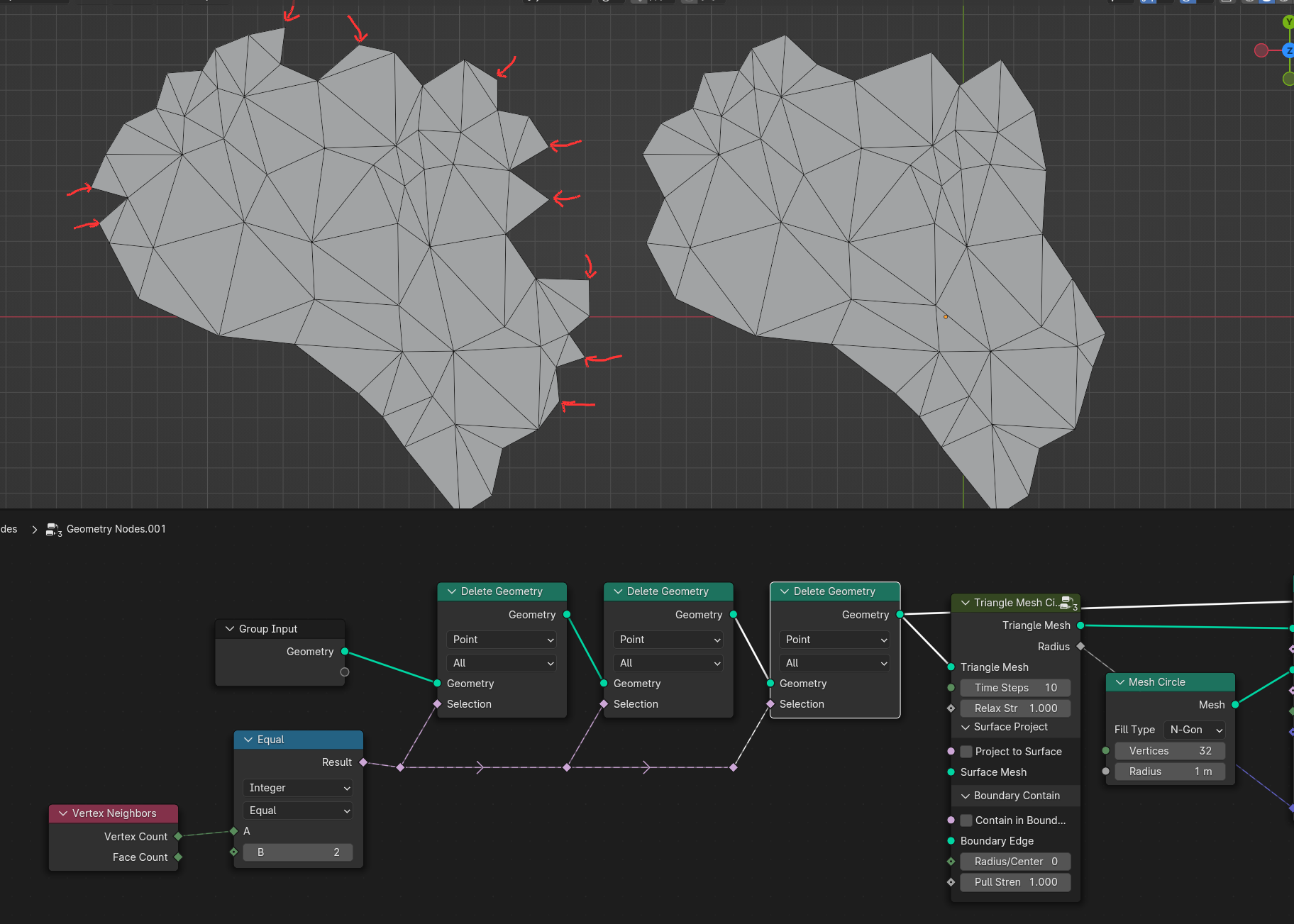
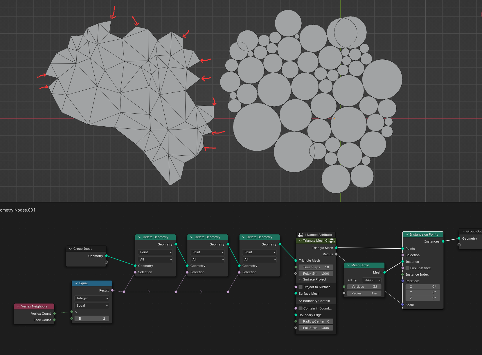
Boundary trianges that has only 2 vertex neighbors will not move during simulation and can give bad packing results
Best is to avoid these triangles when generating triangular mesh if posible, if not simple solution would be deleting vertices with only 2 neighbors untill no more bad triangles left
In some cases circles on edges can overlap
Surfaces that has holes inside will not pack well